Lecture
By location relative to the planes of the projections, the planes are divided into planes of general and particular position.
The planes of general position include planes that are non-parallel and non-perpendicular to any of the projection planes. In a complex drawing (see Fig. 88), projections of elements that define a plane, as a rule, occupy a common position.
The planes of a particular position include planes parallel or perpendicular to one of the projection planes.

Fig. 89
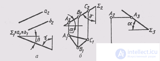
In turn, the planes of a particular position are divided into projecting planes and level planes . To the projecting planes are the planes, perpendicular to one of the planes of the projections. All projecting planes will be denoted by the letter E. Projection planes can be perpendicular to P 1 , P 2 or P 3 . Depending on this, horizontally projecting planes are distinguished when Sum_ | _ П 1 ; frontally projecting planes when Sum_ | _ П 2 ; profile projecting planes when Sum_ | _ П 3 ;
A projecting plane is distinguished by the fact that its projection on the projection plane, which is perpendicular to it, is always depicted as a straight line and figures lying in the projecting plane. The projection of the plane, expressed in a straight line, completely determines the position of the plane relative to the planes of the projections. For example, in fig. 89, and a complex drawing of a plane I defined by two parallel straight lines. It can be seen from the figure that I (a \\ b) is a horizontally projecting plane and is located at an angle P to the frontal plane of the projections and at an angle y with the frontal plane of the projections.
In fig. 89, b shows a complex drawing of the Sum plane, which makes an angle a with a horizontal plane of projections and an angle y with a frontal plane of projections. This can be written as follows: ABC ~ A 2 ~ Sum 2 , B 2 ~ Sum 2 , C 2 ~ Sum 2 .
The presence of a degenerate projection makes it possible to set the projecting planes on a complex drawing with only one projection. In fig. 89, through a point A, a profile-projecting plane (Sum_ | _P 3 ) is drawn at an angle a to P 1 .
All images located in a given plane, on a plane that are not perpendicular to it, are projected with distortion.
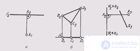
Level planes include planes parallel to one of the projection planes. They can be considered double projecting.

Fig. 90
planes, since in their complex drawing two projections have the form of a straight line at right angles to the communication line, and the third projection gives an image of all the elements lying in this plane in full size. Level planes are usually denoted: Г - horizontal level plane; Ф - frontal plane level; U - profile
level plane. In fig. 90, and given a comprehensive drawing of the plane of the horizontal level (G || P 1 ); in fig. 90, b shows a comprehensive drawing of the frontal level plane (F || P 2 ), F e ABC, A 2 B 2 C 2 - the true value of the triangle ABC; in fig. 90, c shows a comprehensive drawing of a profile projecting plane (U || P 3 , u aA; A ~ a).
Level planes are distinguished by the fact that on the projection plane, which is perpendicular to them, they are projected into a straight line on which points, lines and figures are located in the level plane. These lines are degenerate projections of a given plane. All images of this plane are projected without distortion, that is, full-size, onto the plane of projections parallel to a given plane.
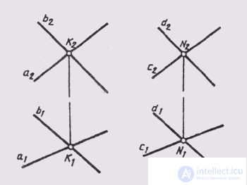
Two planes in space can be parallel or intersect. Parallel will be planes if one of them is defined by intersecting straight lines parallel to intersecting

Fig. 91
giving the second plane; in fig. 91 shows parallel planes: Sum (ahb) and Sum 2 (cxd), with a || c, ab || d.
If the planes intersect, their intersection line is straight. Planes perpendicular to each other represent the case of their intersection when the angle between the planes is 90 °.
The construction of the lines of intersection of the planes is considered in §62.
Comments
To leave a comment
Descriptive Geometry and Engineering Graphics
Terms: Descriptive Geometry and Engineering Graphics