Lecture
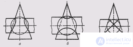
When constructing the line of intersection of the surfaces of revolution - the cone and the cylinder - there may be various cases. In fig. 136 shows three cases of intersection of the cylinder and the cone of rotation. In the first case (Fig. 136, a) the cylinder cuts into a cone, because if you enter a sphere into the cone with the center at the point of intersection of the axes of the surfaces, then its radius will be greater than the cylinder radius. All forming cylinder intersect with the surface of the cone. In the second (Fig. 136, b), the cone cuts into the cylinder, since the sphere inscribed into the cylinder intersects the cone. All cone forming cross the surface of the cylinder. In the third (Fig. 136, c) the sphere inscribed on one surface touches the second surface, and all the generators of both the cylinder and the cone participate in the intersection. In this case, the spatial line of intersection of the surfaces splits into two flat curves (ellipses).
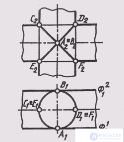
This position is confirmed by the Monge theorem: if two surfaces of the second order are described around a third surface of the second order, then they intersect along two curves of the second order. Such surfaces have two points where they touch each other, or they say that surfaces have a double touch. The line of intersection of two surfaces of rotation with a double touch, splits into two curves of the second order, the planes of which pass through the straight line connecting the touch points (Fig. 137). Two cylindrical surfaces of rotation of the same diameter touch each other at points A and B or have common tangent planes F 1 and F 2 . The line AB occupies the front projection position, therefore the planes of the intersection curves will be front projection. ACBF and AEBD ellipses are depicted.

Fig. 136

Fig. 137

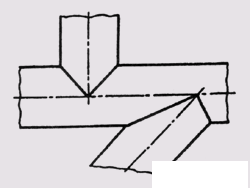
Fig. 138

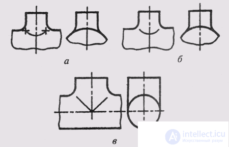
Fig. 139
line segments on the frontal plane of the projections and circles that coincide with the degenerate projections of the vertical cylinder, on the horizontal plane of the projections. This position is widely used in the image of intersecting pipes or holes of the same diameter (Fig. 138).
In the construction of technical parts, often when crossing surfaces of revolution, a mating surface is used, which provides a smooth transition from one surface to another (Fig. 139, a, b, c).
In order not to build two closely spaced lines of intersection of the mating surface with the main surfaces, one line is conventionally drawn in the drawing, making it a thin solid line.
This line is called the transition line. The transition line ends at the intersection points of the outline lines of the main surfaces (Fig. 139, a) and is replaced by simpler (circular) curves.
Comments
To leave a comment
Descriptive Geometry and Engineering Graphics
Terms: Descriptive Geometry and Engineering Graphics