Lecture
The image of an object mentally dissected by one or several planes is called a slit. The mental dissection of an object refers only to this section and does not entail changes in other images of the same object. The section shows what is produced in the section plane and what is located behind it.
Cuts are used to image the internal surfaces of the object to avoid a large number of dashed lines that can overlap each other with a complex internal structure of the subject and make it difficult to read the drawing.
To make the cut, it is necessary: in the right place of the object to mentally draw a cutting plane (Fig. 173, a); mentally discard part of the object between the observer and the cutting plane (fig. 173, b), project the remaining part of the object onto the corresponding projection plane, execute the image either on the site of the corresponding view, or on the free field of the drawing (fig. 173, c); flat shape, lying in the cutting plane, shade; if necessary, give the designation of the incision.
Depending on the number of cutting planes, the sections are divided into simple ones - with one cutting plane, complex ones - with several cutting planes.
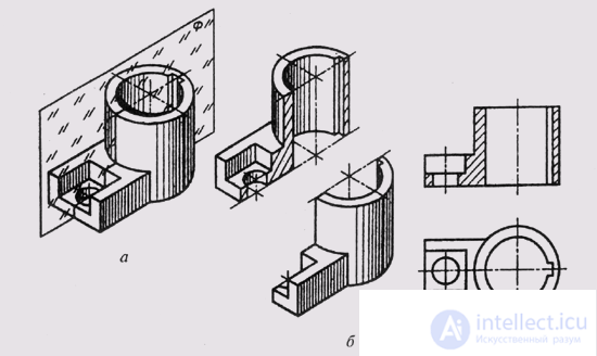
Fig. 173
Depending on the position of the cutting plane relative to the horizontal plane of the projections, the cuts are divided into:
horizontal - the cutting plane is parallel to the horizontal plane of the projections;
vertical - cutting plane perpendicular to the horizontal plane of the projections;
inclined - the cutting plane is with the horizontal plane of the projections an angle different from the direct one.
A vertical section is called frontal if the section plane is parallel to the frontal plane of the projections, and profile if the section plane is parallel to the profile plane of the projections.
Complicated cuts are stepped, if the cutting planes are parallel to each other, and broken, if the cutting planes intersect with each other.
The cuts are called longitudinal, if the cutting planes are directed along the length or height of the object, or transverse, if the cutting planes are directed perpendicular to the length or height of the object.
Local cuts are used to identify the internal structure of the object in a separate limited space. Local incision stands out in the form of a solid wavy thin line.
The rules provide for the designation of cuts.
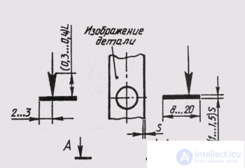
Fig. 174
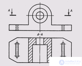
Fig. 175
The position of the cutting plane is indicated by an open section line. The initial and final strokes of the section line should not intersect the contour of the corresponding image. At the initial and final strokes you need to put the arrows indicating the direction of the gaze (Fig. 174). Arrows should be applied at a distance of 2 ... 3 mm from the outer end of the stroke. With a complicated section, the strokes of an open section line are also carried out at the bends of the section line.
Near the arrows, indicating the direction of view from the outside of the angle formed by the arrow and the stroke of the section line, the capital line of the Russian alphabet is put on the horizontal line (Fig. 174). Letter symbols are assigned in alphabetical order without repetitions and without gaps, except for the letters I, O, X, b, b, b.
The cut itself should be marked with an “A - A” type (always in two letters, with a dash).
If the cutting plane coincides with the plane of symmetry of the object, and the section is made on the site of the corresponding type in the projection connection and is not separated by any other image, then for horizontal, vertical and profile sections, it is not necessary to mark the position of the section plane and not to accompany the section. In fig. 173 frontal incision is not marked.
Simple inclined cuts and complex cuts always denote.
Consider typical examples of the construction and designation of cuts in the drawings.
In fig. 175 made a horizontal section "A - A" in place of the top view. The plane figure lying in the section plane, the section figure, is hatched, and the visible surfaces located
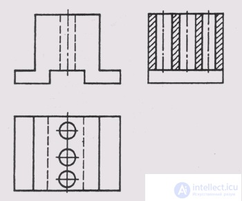
Fig. 176
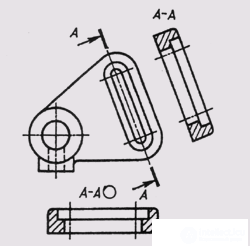
Fig. 177
under the secant plane, bounded by contour lines and not shaded.
In fig. 176 a profile section is made on the place of the view on the left in projection connection with the main view. The secant plane is the profile plane of symmetry of the object, so the cut is not denoted.
In fig. 177 a vertical section "A - A" is made, obtained by a secant plane, not parallel to either the frontal or profile planes of the projections. Such cuts can be constructed in accordance with the direction indicated by the arrows (Fig. 177), or located in any convenient place in the drawing, as well as turning to the position corresponding to that adopted for the given object on the main image. In this case, the sign O is added to the cut designation.
The inclined section is made in Fig. 178. It can be drawn in
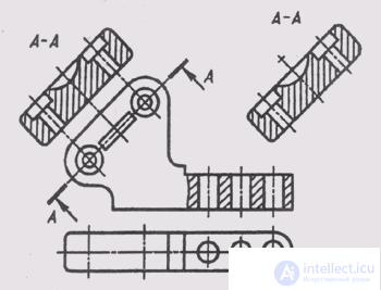
Fig. 178
projection connection in accordance with the direction indicated by the arrows (Fig. 178, a), or locate anywhere in the drawing (Fig. 178, b).
In the same figure, on the main view, a local section is made showing the through cylindrical holes on the base of the part.
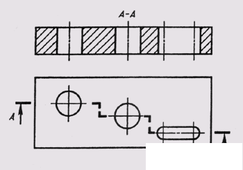
Fig. 179
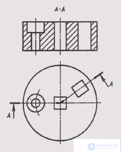
Fig. 180
In fig. 179 in place of the main view, a complex front stepwise section is drawn, made of three frontal parallel planes. When performing a stepped incision, all parallel cutting planes are mentally combined into one, that is, a complex incision is made out as simple. In a complex section, the transition from one sectional plane to another is not reflected.
When building broken cuts (fig. 180), one cutting plane is placed parallel to some main plane of projections, and the second cutting plane is rotated to align with
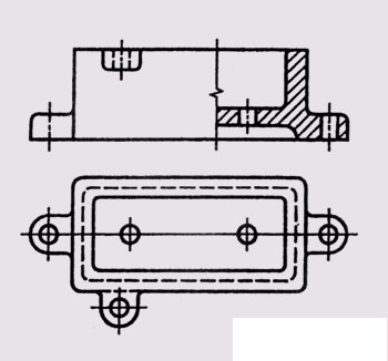
Fig. 181
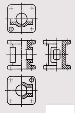
Fig. 182
first. Together with the secant plane, the sectional figure located in it is turned and the incision is made in the rotated position of the sectional figure.
The connection of a part of a view with a part of a cut in one image of an object according to GOST 2.305-68 is allowed. In this case, the border between the view and the cut is a solid wavy line or a thin line with a break (Fig. 181).
If half of the view and half of the section are connected, each of which is a symmetrical figure, then the line of separation between them is the axis of symmetry. In fig. 182 four detail images are made, with half of the view connected with half of the corresponding section in each of them. On the main view and on the left, the cut is placed to the right of the vertical axis of symmetry, and in the top and bottom views - to the right of the vertical or bottom of the horizontal axis of symmetry.
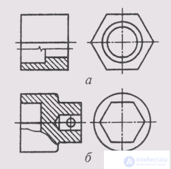
Fig. 183
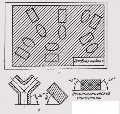
Fig. 184
If the contour line of the object coincides with the axis of symmetry (Fig. 183), then the boundary between the view and the section is indicated by a wavy line, which is carried out in such a way as to preserve the image of the edge.
Shading a sectional shape entering the cut must be carried out in accordance with GOST 2.306-68. Non-ferrous, ferrous metals and their alloys are denoted by shading in section with solid thin lines from S / 3 to S / 2, which are held parallel to each other at an angle of 45 ° to the lines of the drawing frame (Fig. 184, a). Hatching lines can be applied with a slope to the left or to the right, but in the same direction on all images of the same part. If the lines of the hatching are drawn at an angle of 45 ° to the lines of the frame of the drawing, then you can arrange the lines of the hatching at an angle of 30 ° or 60 ° (fig. 184, b). The distance between parallel lines of hatching is chosen in the range from 1 to 10 mm, depending on the area of hatching and the need to vary the hatching.
Non-metallic materials (plastics, rubber, etc.) are indicated by hatching with intersecting mutually perpendicular lines (hatching “in a cage”), inclined at 45 ° to the frame lines (Fig. 184, c).
Consider an example. Having performed the frontal section, we will combine half of the profile section with half of the left view of the object specified in fig. 185, a.
Analyzing this image of the object, we come to the conclusion that the object is a cylinder with two through horizontal prismatic and two vertical internal
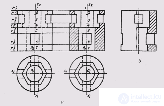
Fig. 185
holes, of which one has the surface of a regular hexagonal prism, and the second - a cylindrical surface. The lower prismatic hole intersects the surface of the outer and inner cylinder, and the upper tetrahedral prismatic hole intersects the outer surface of the cylinder and the inner surface of the hexagonal prismatic hole.
The frontal section of the object (Fig. 185, b) is performed by the frontal plane of the symmetry of the object and is drawn in the place of the main view, and the profile section is drawn by the profile plane by the symmetry of the object, therefore, neither one nor the other is necessary. The left side view and the profile section are symmetrical figures; their halves could be separated by the axis of symmetry, if not for the image of the edge of the hexagonal hole coinciding with the axial line. Therefore, we separate part of the view to the left of the profile section with a wavy line, depicting most of the section.

Comments