Lecture
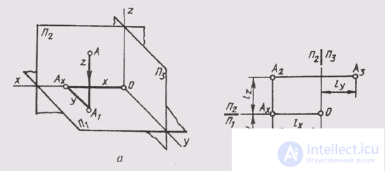
The three main projection planes (P 1 _ | _P 2 _ | _ P 3 ) can also be considered as coordinate planes. Then the axes of the projections become the coordinate axes: the x- axis x, P 1 / P 3 —an axis of coordinates y, P 2 / P 3 —Other application z.
The origin (point O) is located at the point of intersection of the axes of the coordinates (Fig. 68, a).
To assign point A to the natural coordinate system Oxyz, it is necessary to construct an orthogonal projection of point A on the xOy plane . Then the projection A 1 is orthogonal to the projection on the x axis to the point A x . Then we get the spatial coordinate polyline AA 1 A X O, the segments of which are parallel to the axes of coordinates and, accordingly, are called: OA X - the abscissa segment; And Х А 1 - ordinate segment; And 1 And - a segment of applicati.
Measuring the coordinate segments of a unit of length l , we obtain three abstract numbers - three coordinates of point A:
x = OA X abscissa; y = A x A 1 - ordinate; z = AA 1 - applicate.
If a point is given by its own coordinates A (x, y, z), then it is possible to construct its complex drawing by specifying the corresponding unit of length l (for example, l = 1 mm). The abscissa of the point determines the position

Fig. 68
vertical communication line (Fig. 68, b). The horizontal projection of a point is determined by the magnitude of the ordinate, and the frontal projection is determined by the magnitude of the applicants.
Comments
To leave a comment
Descriptive Geometry and Engineering Graphics
Terms: Descriptive Geometry and Engineering Graphics