Lecture
You can build projections of objects in the drawing in two ways: central and parallel.
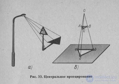
The essence of the central projection method is that all the rays projecting the object emanate from a single point P, called the center of projections (Fig. 44). The obtained projections A ', B', C ' are called the central projections of points A, B, C.
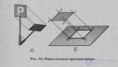
The essence of the parallel method lies in the fact that all projecting rays are parallel to the predetermined direction 5, and therefore each other (Fig. 45). This can be likened to the case of the central projection method, when the center of the projections S is removed to infinity and all the projecting rays become parallel.
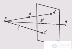
Fig. 44
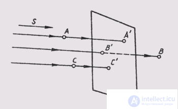
Fig. 45
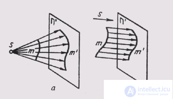
Fig. 46
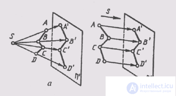
Fig. 47
mi When constructing projections A ', B', C 'in this way, they are called parallel projections of points A, B, C.
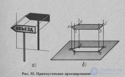
When projecting, a set of projecting rays form various geometric shapes. When projecting a straight line, this is a plane (fig. 46) when projecting a broken line — the surface of a prism or pyramid (fig. 47), while projecting a curved line — a conical or cylindrical surface (fig. 48). Unlike projected figures, these figures are called projectors.
The basis of the rules for constructing images on the drawing is the projection method. To find out what constitutes this method, refer to the examples.
Comments
To leave a comment
Descriptive Geometry and Engineering Graphics
Terms: Descriptive Geometry and Engineering Graphics