Lecture
Permanent joints are widely used in mechanical engineering. These include welded, riveted, soldered, glue. This also includes compounds obtained by testing, pouring, flaring (or rolling), coreing, stitching, landing with tension, etc.
Welded joints are obtained by welding. Welding is the process of obtaining a permanent connection of solid objects consisting of metals, plastics or other materials, by locally heating them to a molten or plastic state without application or with the use of mechanical forces.
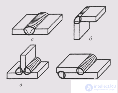
Fig. 242
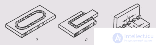
Fig. 243
A welded joint is a set of products connected by welding.
A welded seam is a material hardened after melting. Metal weld differs in its structure from the metal structure of the welded metal parts.
According to the method of the relative positioning of the parts to be welded, butt joints (fig. 242, a), angular (fig. 242, b), T-shaped (fig. 242, c) and overlap (fig. 242, d) are distinguished . The type of joint determines the type of weld. Weld seams are divided into: butt, corner (for corner, T-joints and lap joints), punctures (for lap joints, spot welding).
By their length, welds can be: continuous along a closed contour (Fig. 243, a) and along an open contour (Fig. 243, b) and intermittent (Fig. 243, c). Intermittent seams have equal length of the boiled areas with equal intervals between them. In two-sided welding, if the welded sections are located opposite each other, such a seam is called a chain (Fig. 244, a), if the sections alternate, then the seam is called chess (Fig. 244, b).
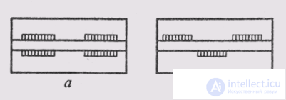
Fig. 244
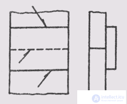
Fig. 245
Thin-sheet structures can be welded without prior preparation of the edges being welded. The shape of the preparation of edges depends on the thickness of the parts to be welded, the position of the seam in space and other data.
The terms and definitions related to welding are set by GOST 2.601-68. The most common type of welding is electric welding, which can be manual, semi-automatic and automatic.
Welding methods, types and structural elements of welds are defined by the relevant standards. Conditional images and designation of seams of welded joints are carried out in accordance with GOST 2.312-72 . Welded seams are represented by solid main lines, if the seam is visible, and dashed, if the seam is invisible (Fig. 245). From the image of the seam hold one-way arrow with a line-callout. The weld designation symbol is written above the leader of the line-leader, if the seam is visible, i.e., the front side of the seam is shown (Fig. 246, a, 6), and under the shelf-line, if the seam is invisible, i.e. reverse side of the seam (Fig. 246, c, d).
The structure of the symbol of the weld is shown in Fig. 247, where:
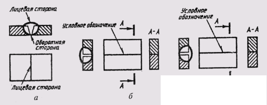
Fig. 246
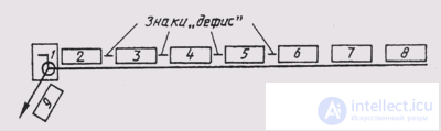
Fig. 247
1 - auxiliary signs, O - a seam on a closed contour, | - mounting seam;
2 - designation of the standard for the type and structural elements of the seam;
3 - alphanumeric designation of a seam according to this standard;
4 - symbol of the welding method according to the standard for this seam;
5 - auxiliary sign A - the triangle and the size of the seam leg;
6 - dimensions in mm of a discontinuous seam with signs: / - for a chain seam and Z - for a chess seam or] - a sign of an unclosed welding contour;
7 - auxiliary marks (Q or co) of the weld;
8 - designation of the roughness of the mechanically treated seam (see §94);
9 - an indication of the control seam.
Examples of the symbol of welds:
GOST 14806—80 = T5 - RiZ = 1–6–50 Z 100 - the seam is made by electric arc welding of aluminum, a T-fitting joint, T5, manual welding in protective gas RIZ, a 6 mm A6 seam leg, a seam of chess, the length of the welded section 50 mm, pitch - 100 mm (50 Z 100).
GOST 5264-80 — C18 - the seam is performed by manual electric arc welding during installation 1, butt weld (C 18) along an open loop.
If there are several identical seams in the drawing, the designation is applied only to one seam, and therefore a sequence number is assigned to the seam with the number of these seams attached to the leader line. All other stitches of this type have on the shelf the leader lines the designation of the sequence number of the seam (fig. 248), if the front side of the seam is indicated, and under the shelf of the leader line, if the reverse side of the seam is indicated. In fig. 248 designation number 1 two corner seams made by manual arc welding, from the front side, the seam reinforcement must be removed by Q machining, after which the seam roughness must correspond to the sixth class (Ra = 2.5 μm).
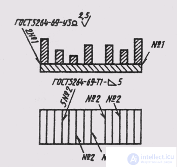
Fig. 248
Five welds No. 2 are performed as single-sided Tic-welds with a 5 mm A5 arm, manual arc welding.
If all the seams in the drawing are performed according to one standard, then its number is not entered into the seam designation, but written down in the technical requirements in the field of the drawing according to the type “Welded Seams according to GOST ...”.
If all the seams in the drawing are the same, then the seam symbol may not be applied to the images, but make one entry of the seam symbol of technical requirements, for example: “Welded seams according to GOST 5264—80 — U5 — A4”.
Riveted joints are used in structures exposed to high temperature, corrosion, vibration, as well as in compounds of poorly welded metals or in compounds of metals with non-metallic parts. Such compounds are widely used in boilers, railway bridges, some aircraft structures and in light industry.
At the same time, in a number of industries with the improvement of the technology of welded production, the use of riveted joints is gradually reduced.
The main fastening element of riveted joints is a rivet. It is a short cylindrical rod of circular cross section, at one end of which there is a head (fig. 249). The heads of the rivets may have a spherical, conical
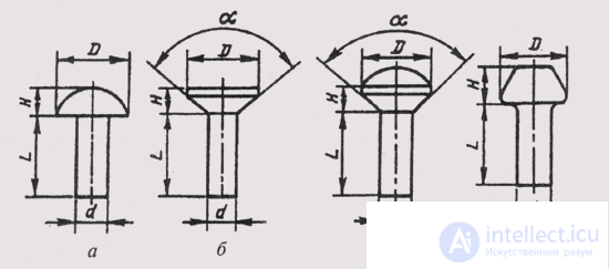
Fig. 249
Pic.250
or conic-spherical shape. Depending on this, semicircular heads are distinguished (Fig. 249, a), secret (Fig. 249, b), semi-secret (Fig. 249, c), flat (Fig. 249, d).
In the assembly drawings, the heads of rivets are depicted not by their actual dimensions, but by relative sizes, depending on the diameter of the rivet shank d.
The technology of the rivet connection is as follows. In the connected parts make holes by drilling or in another way. The head of the rivet is inserted into the through hole of the parts to be joined against the stop. And the rivet can be hot or cold. The free end of the rivet extends beyond the part by about 1 , 5d. It is riveted with blows or strong pressure and creates a second head (fig. 250).
The diameter of the cores of the rivets is chosen according to special tables. Approximately it is assumed to be equal to the thickness of the parts to be joined. The length of the rod rivets are also taking into account the thickness of the parts to be joined and the allowance. Approximately it is 1 , 5d.
Riveted seams can be single-row and multi-row. Rivets are usually located in a row at the same distance. The location of the rivets in the seam can be ordinary and chess. The joined parts in riveted joints can be made with overlap or end-to-end with overlays.
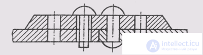
In the drawings indicate all structural dimensions of the seams riveted joints. It does not draw all the rivets of the connection. Usually show one or two of them, and the location of the rest is indicated by the intersection of the axes (Fig. 251).
Riveted seams have their own designations, which are applied on the drawings. The designation indicates the diameter (d) and the length (/) of the rivet rod, the metal group and the number of the GOST that defines the shape of the head and the coating.
For example, a rivet having a semicircular head, length d = 25 mm, rod diameter d = 10 mm, made of metal of the ОО group, without coating has the designation: Rivet 10x25 GOST 10299-80.
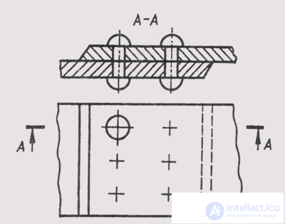
Fig. 251
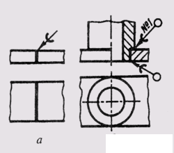
Fig. 252
Solder joints are widely used in instrument making, electrical engineering. When soldered, the parts to be connected are heated to a temperature that does not cause them to melt. The gap between the connected parts is filled with molten solder. Solder has a lower melting point than solder materials. For soldering use soft solders POS - tin-lead according to GOST 21930-76 and GOST 21931-76 and solid solders Per - silver according to GOST 19738-74.
Solder on the types and cuts depict a solid line with a thickness of 2S. For the designation of soldering, a conventional sign is used (Fig. 252, a) - an arc with a bulge to the arrow that is drawn on the leader line indicating the soldered seam. If the seam is made along the perimeter, then the leader line is terminated with a circle. The number of stitches indicate the leader line (Fig. 252, b).
The brand of solder is recorded either in the technical requirements or in the specification in the “Materials” section (see § 101).
Glue connections allow you to combine a variety of materials. The glue seam, as well as the soldered one, is depicted according to a 25-gauge solid line. A symbol is drawn on the leader line (fig. 253, a), resembling the letter K. If the seam is made around the perimeter, then the leader line is completed with a circle (fig. 253, b). The glue mark is recorded either in the technical requirements or in the specification in the "Materials" section.
Crimping (reinforcement) protects the connected elements from corrosion and chemical exposure to a harmful environment, performs insulating functions, reduces the mass of the product (Fig. 254), and saves materials.
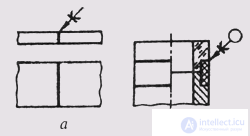
Fig. 253
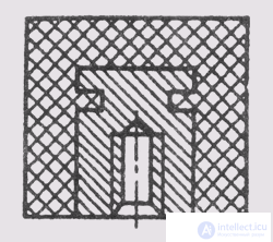
Fig. 254
Rolling and coreing is carried out by the deformation of the parts to be joined (Fig. 255, a, b). Stitching with threads, metal brackets is used to join paper sheets, cardboard, various fabrics.
GOST 2.313-82 establish the symbols and images of the seams of one-piece joints obtained by soldering, gluing, stitching.
The connection of parts by fitting with tension is ensured by a system of tolerances and landings with a certain temperature regime before welding parts.
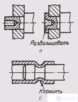
Fig. 255

Comments
To leave a comment
Descriptive Geometry and Engineering Graphics
Terms: Descriptive Geometry and Engineering Graphics