Lecture
The surface of any part, even if it is very carefully processed, has irregularities in the form of protrusions and depressions. Moreover, such irregularities in some parts can be detected even by unarmed
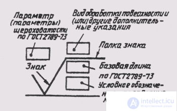
Fig. 275
with one eye, in others - only with the help of special devices. The magnitude of the roughness on the surface of the part is measured in micrometers (μm).
The combination of irregularities that form the surface relief, regardless of the method, is called roughness.
The surfaces of the parts are formed as a result of their processing. As a rule, the working surfaces of the parts are treated more qualitatively than non-working ones.
The surface roughness is regulated by GOST 2789-73 and GOST 2.309-73. The standard sets the following parameters for surface roughness characteristics:
R a is the arithmetic average deviation of the profile;
R z - the height of profile irregularities at ten points;
Rmax - the greatest height of profile irregularities;
S m - the average step of irregularities;
S - the average step of irregularities at the tops, etc.
Established 14 classes of surface roughness. The smaller the roughness, the higher the roughness class. The roughness classes from the first to the fifth, as well as the 13th and 14th grades are determined by the R z parameter, all other classes (from the sixth to the twelfth inclusive) are determined by the R a parameter, the symbol of which is not written, but only a quantitative characteristic is written.
In fig. 275 shows the structure of the designation of surface roughness.
In fig. 276 depicts signs that are used in the designation of roughness. The size h is taken equal to the height of the dimensional numbers in the drawing, and the size H is equal to (1, 5, ... 3) h.
The sign in fig. 276, and is used to designate the surface roughness, the type of processing of which is not specified by the designer. The sign in fig. 276, б designates the surface roughness formed by removing the metal layer (turning, milling, drilling, etc.). The roughness of the surface in the state of delivery (rolled, forged, cast, etc.) and not processed according to this drawing is indicated by the sign shown in fig. 276, c.
The designations of surface roughness in the image details are placed on the contour lines, extension lines or shelves of
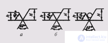
Fig. 276
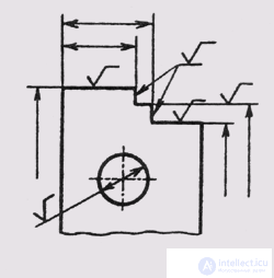
Fig. 277
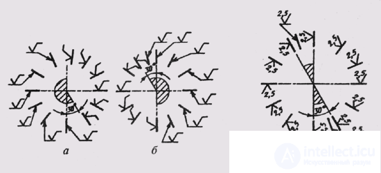
Fig. 278
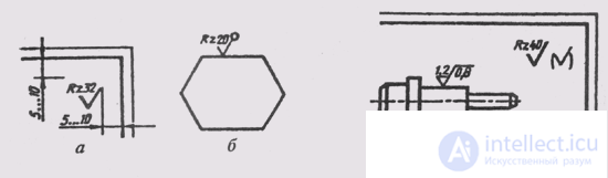
Fig. 279
nii-callouts (Fig. 277). Apply signs of roughness in the image, depending on the location of the surface and the presence of the shelf at the sign (Fig. 278).
When specifying the same roughness for all surfaces, details of the roughness designation are placed in the upper right corner of the drawing and are not applied to the image (Fig. 279, a). The dimensions and thickness of the line of the mark taken out in the upper right corner should be 1.5 times larger than in the notation in the image.
In the case of the same roughness for the predominant part of the surfaces of the part, the roughness is applied as shown in fig. 279, b. This means that all surfaces on which there is no roughness designation have a roughness with an amount of asperities indicated in the upper right corner of the drawing. The dimensions of the sign in brackets should be the same with the signs on the images.
If the roughness of the surfaces forming the contour of the part should be the same, then the roughness marking is applied as shown in fig. 279, c.

Comments
To leave a comment
Descriptive Geometry and Engineering Graphics
Terms: Descriptive Geometry and Engineering Graphics