Lecture
When performing technical drawings in some cases it is necessary, along with the image of objects in rectangular projections, to have their visual images. It is necessary to provide an opportunity to more fully identify the constructive solutions incorporated in the image of the object, correctly represent its position in space, estimate the proportions of its parts and dimensions.
Illustrative images in some drawings can be applied independently of rectangular images, for example, when depicting power supply and heat supply circuits of buildings and structures.
There are various ways to build visual images. This includes axonometric, affine and vector projections, as well as
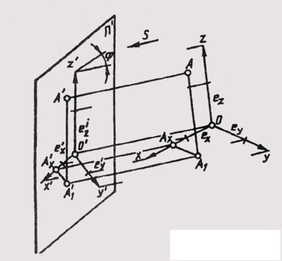
Fig. 156
ney prospect. In this tutorial, only axonometric projections are considered.
The construction of axonometric projections is that a geometric figure, along with the axes of rectangular coordinates to which this figure is related in space, is projected in parallel (rectangular or oblique) ways onto a selected projection plane. Thus, the axonometric projection is a projection on one plane. The direction of projection is chosen so that it does not coincide with any of the coordinate axes.
When constructing axonometric projections, the depicted object is rigidly connected with the natural coordinate system Oxyz (see § 37). In general, the axonometric drawing is obtained consisting of a parallel projection of the object, supplemented by an image of coordinate axes with natural scale segments along these axes. The name "axonometry" comes from the words - axon - axis and metreo - measured .
The formation of an axonometric projection is considered on the example of constructing an axonometric point A, referred to the natural coordinate system Oxyz (Fig. 156). The natural coordinates of point A are obtained by measuring the segments of the coordinate polygonal line AA 1 A X O with the natural scale e. When parallelly projecting along the direction S on the plane of axonometric projections I 1, we get an axonometric projection A 1 of this point, an axonometric projection A 1 A 1 1 A 1 x O coordinate the broken line and axonometric projection of the UUUU natural coordinate system, on the axes of which there will be single axonometric scale segments e 1 x e 1 y e 1 z .
Axonometric projection A 1 1 of the horizontal projection of point A (primary) is called the secondary projection of point A. The combination of all these projections is the axonometry of point A.
In the axonometric drawing, the secondary and axonometric projections of the object provide metric certainty and reversibility of the single-image image.
In axonometric projections, all properties of parallel projections are retained (see § 28).
In practice, measurements along axonometric axes are performed in the same units - millimeters; therefore, single natural scale segments and their axonometry are not indicated in the drawings.
Axial distortion coefficients in axonometry are determined by the ratio of axonometric coordinate segments to their natural size for the same units of measurement.
Natural distortion factors denote: on the x axis : u = O 1 A 1 x / OA x ; y-axis: v = A 1 x A 1 1 / A x A 1 ;
on the z axis: w = A 1 1 A 1 / A 1 A ;

Comments
To leave a comment
Descriptive Geometry and Engineering Graphics
Terms: Descriptive Geometry and Engineering Graphics