Lecture
A graphic document containing an image of an assembly unit and other data necessary for its assembly (manufacturing) and control is called an assembly drawing.
The assembly drawing is carried out at the stage of development of working documentation on the basis of the drawing of the general form of the product. Based on GOST 2.109-73, the assembly drawing should contain:
an image of the assembly unit, giving an idea of the location and interrelation of the component parts connected according to this drawing and ensuring the possibility of assembling and controlling the assembly unit;
dimensions and other parameters and requirements that must be met and controlled according to this drawing;
indications of the nature of the mating of detachable parts of the product, as well as indications of the method of joining permanent joints, such as welded, soldered, etc .;
item number of components included in the product;
the main characteristics of the product;
overall dimensions, installation, connecting, as well as the necessary reference dimensions.
The number of images on the assembly drawing depends on the complexity of the product design. A training assembly drawing is usually made in two or three main images using cuts. It is recommended to connect half of the view with a half cut in the presence of symmetry of the look and cut of the product.
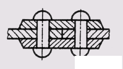
Fig. 306
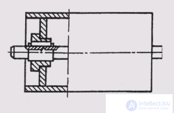
Fig. 307
Sections and cross-sections in the assembly drawings serve to identify the internal structure of the assembly unit and the relationship of its parts.
The section in the assembly drawing is a set of sections of the individual parts included in the assembly unit. Hatching of the same part in sections on different images is performed in the same direction, maintaining the same distance (step) between the lines of hatching. Hatching of adjacent parts from the same material is diversified by changing the direction of the hatching, shifting the hatching lines or changing the hatching pitch (fig. 306). Welded, brazed or glued products from the same material, assembled with other products, in cuts and sections, hatch like a monolithic body, showing the boundaries between the parts of the welded product with solid main lines (Fig. 307). Balls in sections and sections are always shown undissected. Screws, bolts, studs, pins, bolts, washers, nuts and other standard fasteners in a longitudinal section are shown untrimmed. Non-corpore shafts, spindles, handles, connecting rods, etc. with a longitudinal section are also depicted undissected (Fig. 308).
On assembly drawings it is allowed not to show chamfers, roundings, grooves, recesses, protrusions, corrugations, braid and other small elements. It is allowed not to depict the gaps between the rod and the hole. If it is necessary to show the component parts of the product, closed with a lid, cover, shield, etc., then the closing products can not be depicted, and above the image to perform an inscription like "Cover pos. 5 not shown.
Products from the helical spring, depicted only by the cross section of the coils, are depicted only up to the zone conditionally covering these products and defined by the axial lines of the cross section of the coils (fig. 309).
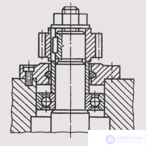
Fig. 308
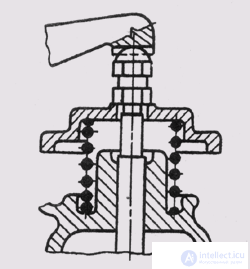
Fig. 309
When performing assembly drawings, the conventions and simplifications established by the standards for the rules for the execution of drawings of various products are observed.
On the assembly drawing it is allowed to depict the moving parts of the product in the extreme or intermediate position with the corresponding cuts, using thin dash-dotted lines with two points (Fig. 310). For the image of neighboring products - "furnishings" - use thin solid lines (Fig. 311).
On the assembly drawings put the following dimensions ..
Overall dimensions characterizing the three dimensions of the product. If one of the dimensions is variable due to the movement of the moving parts of the product, then the dimensions indicate the extreme positions of the moving parts (Fig. 312).
Mounting dimensions that indicate the interconnection of parts in an assembly unit, such as the distance between the axes of the shafts, mounting clearances, etc.
Fig. 310
Fig. 311
Installation dimensions that determine the size of the elements on which the product is installed at the installation site or attached to another product, such as the dimensions of the circles and the diameters of the bolt holes, the distance between the axes of the foundation bolts, etc.
The operational dimensions that determine the design, structural characteristics of the product, such as the diameters of the bore holes, the size of the thread on the connecting elements, etc.
The assembly drawings also indicate the dimensions of the holes for fasteners, if these holes are made during the assembly process.
All other parts of the assembly unit are numbered in accordance with the item numbers specified in the specification of this assembly unit. Position numbers indicate on the shelves of leader lines drawn from points on the images of component parts of an assembly unit, which are projected as visible on the main views or in their subsections.
The position numbers are arranged parallel to the main inscription of the drawing outside the contour of the image and grouped together in a column or line by the opportunity on one line (Fig. 312.313, a). Allowed to make a common line-callout with a vertical position (Fig. 313.6). As a rule, the position number is applied to the drawing once. The font size of the position numbers should be 1-2 times larger than the font size of the dimension numbers in this drawing.
Fig. 311
Fig. 312
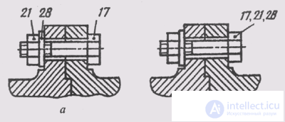
Fig. 313
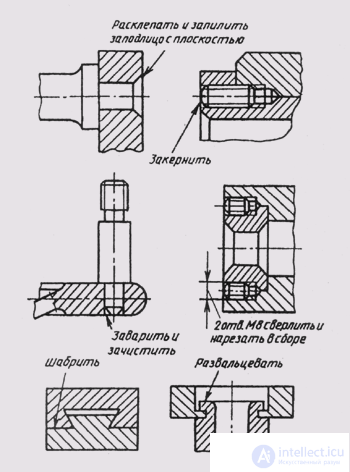
Fig. 314
In the process of assembling the product, some technological, so-called fitting operations are performed. They are performed by joint processing of the parts to be joined or by fitting one part to another at the place of its installation. In these cases, text entries are made on assembly drawings, similar to those shown in Fig. 314.
Many products have typical components. These include, for example, gland seals (Fig. 315). Their soft padding ensures the tightness of the holes through which the moving parts of the product pass. Hemp or flax fiber (Fig. 315, a, 6) or a set of rings made of asbestos, leather, rubber (Fig. 315, c) are used as stuffing. The preloading of the packing is done with a cap nut (Fig. 315, a), a threaded bushing (Fig. 315, b), or a stuffing cap (Fig. 315, c). These parts in the assembly drawings are depicted in a raised position.
Valves have typical fastenings on rods or spindles. Fastenings can be carried out either by crimping the valve (Fig. 316, a), or by a wire bracket (Fig. 316, b), or by a ring of wire (Fig. 316, c). The spindle head can be mounted in the valve slot (Fig. 316, g).
Rolling bearings are standard products. They can be depicted in assembly drawings in a simplified way (Fig. 317, a) without specifying the type according to GOST 2.420-69 or, as shown in Fig. 317, b, - with the image of rings and balls or rollers.
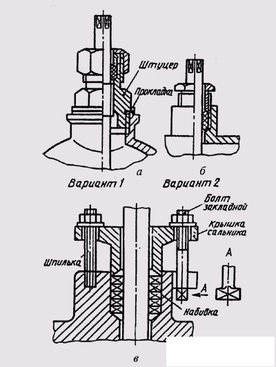
Fig. 315
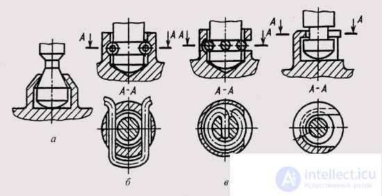
Fig. 316
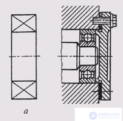
Fig. 317

Comments
To leave a comment
Descriptive Geometry and Engineering Graphics
Terms: Descriptive Geometry and Engineering Graphics