Lecture
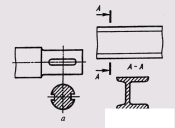
The image of a figure obtained by mental dissection with one or several planes, provided only that which fell into the section plane is shown in the drawing, is called a section. The section differs from the section in that it depicts only what directly falls into the cutting plane (Fig. 186, a). The section, as well as the section, is a conditional image, since the section figure does not exist separately from the object: it is mentally torn off and depicted in the free field of the drawing. Sections are included in the section and exist as separate images.
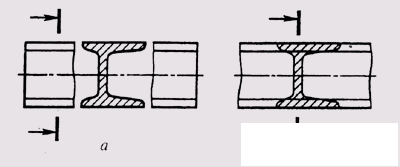
Sechenik not included in the section, divided into rendered (Fig. 186, b) and superimposed (Fig. 187, a). Preference should be given to the sections made, which can be placed in the section between the parts of the same image (Fig. 187, b).
The shape of the cross section is divided into symmetric (Fig. 187, a, b) and asymmetrical (Fig. 186, b).
The contour of the imposed section is drawn in continuous

Fig. 186

Fig. 187

Fig. 188

Fig. 189
the main lines, and the superimposed ones - solid thin, and the outline of the main image at the location of the superimposed section is not interrupted.
The designation of sections in the general case is similar to the designation of sections, i.e. the position of the section plane is shown by section lines on which arrows are applied, giving the direction of sight and denoted by the same uppercase letters of the Russian alphabet. In this case, an inscription of the type “A – A” is performed above the section (see Fig. 186, b).
For asymmetrical superimposed sections or those made in the break of the main image, a section line with arrows is drawn, but not marked with letters (Fig. 188, a, b). Superimposed symmetric section (see Fig. 187, a), a symmetric section made in the main image break (see Fig. 187, b), a pronounced symmetric section made along the cut plane (see Fig. 186, a), make out without drawing the section line.

Fig. 190
If the cutting plane passes through the axis of the surface of revolution bounding the hole or recess, the contour of the hole or recess is drawn completely (Fig. 189, a).
If the cutting plane passes through a non-circular through hole and a cross section is obtained consisting of separate independent parts, then cuts should be applied (Fig. 189, b).
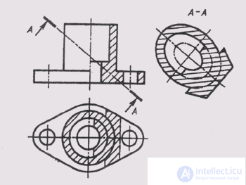
The inclined sections are obtained from the intersection of the object by the inclined plane, which is an angle other than the straight line with the horizontal plane of the projections. In the drawing, the inclined sections are performed according to the type of the removed sections. The oblique section of the object must be constructed as a set of oblique sections of the geometric bodies constituting it. The construction of inclined sections is based on the application of the method of replacing projection planes (see §§ 36, 58).
When drawing an inclined section, it is necessary to determine which surfaces bounding the object are dissected by the section plane, and which lines are obtained from the intersection of these surfaces by this section plane (see § 64). In fig. 190 built inclined section "A - A". The secant plane intersects the base of the object along a trapezoid, the inner and outer cylindrical surfaces - in ellipses, the centers of which lie on the main vertical axis of the object. Reading the shape of an oblique section is simplified if you build a horizontal projection of the oblique section as a superimposed section.
Comments
To leave a comment
Descriptive Geometry and Engineering Graphics
Terms: Descriptive Geometry and Engineering Graphics