Lecture
When performing various images of the subject, GOST 2.305-68 recommends the use of certain conventions and simplifications, which, while maintaining the clarity and visibility of the image, reduce the amount of graphic work.
If the view, section or section are symmetrical figures, then you can only draw half of the image or a little more than half of the image, limiting it with a wavy line (Fig. 192).
It is allowed to simplify depicting the cut lines and transition lines (see § 67); instead of curves, circular arcs and straight lines (Fig. 193, a) are drawn , and a smooth transition from one surface to another is conditionally shown (Fig. 193, b) or not shown at all (Fig. 193, c).
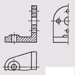
Fig. 192

Fig. 193
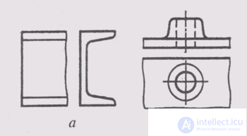
Fig. 194
It is allowed a slight taper or bias depicted increased. In those images where the slope or taper is not clearly detected, only one line is drawn corresponding to the smaller size of the element with a slope (Fig. 194, a) or the smaller base of the cone (Fig. 194, b).
When making cuts, non-truncated shafts, handles, screws, keys, rivets are shown uncut. Balls are always depicted uncut.
Elements such as knitting needles, thin walls, stiffening ribs, are shown uncut in the section if the secant plane is directed along the axis or the long side of such an element (Fig. 195). If there is a hole or recess in such elements, then a local incision is made (Fig. 196, a).
Holes located on the round flange and not falling into the cutting plane are shown in the section as if they are in the cutting plane (Fig. 196, b).
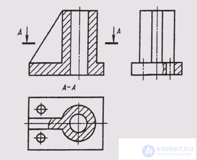
Fig. 195
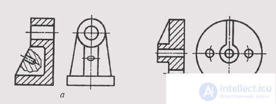
Fig. 196
To reduce the number of images, a part of the object between the observer and the cutting plane is allowed to be depicted as a dash-dotted thickened line (fig. 197).
In more detail, the rules for the depiction of objects are set out in GOST 2.305-68.
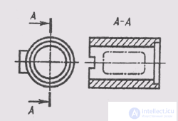
Fig. 197
Comments
To leave a comment
Descriptive Geometry and Engineering Graphics
Terms: Descriptive Geometry and Engineering Graphics