Lecture
The essence of this method is that they replace one of the planes with a new plane located at any angle to it, but perpendicular to the irreplaceable projection plane. A new plane should be chosen so that with respect to it a geometric figure occupies a position that provides for obtaining projections that most satisfy the requirements of the conditions of the problem being solved. To solve some problems, it is enough to replace one plane, but if this solution does not provide the required arrangement of a geometric figure, two planes can be replaced.
The application of this method is characterized by the fact that the spatial position of the specified elements remains unchanged, and the system of projection planes on which new images of geometric images are built changes. Additional projection planes are introduced in such a way that the elements of interest to us are depicted in terms convenient for a specific task.
Consider the solution of the four original problems by replacing the projection planes.
1. Convert the drawing of a straight line of general position so that relative to the new plane of projections the straight line of general position takes the position of a straight level.
A new projection of a straight line corresponding to the task can be constructed on a new plane of projections P 4 , placing it parallel to the straight line itself and perpendicular to one of the main projection planes, that is, from the system of planes P 1 _ | _P 2 go to the system P 4 _ | _ P 1 or P 4 _ | _ P 2 . In the drawing, the new axis of the projections should be parallel to one of the main projections of the line. In fig. 108 an image of a straight line l (A, B) of a general position in the system of planes P 1 _ | _ P 4 , with P 4 || l. New communication lines A 1 A 4 and B 1 B 4 are made
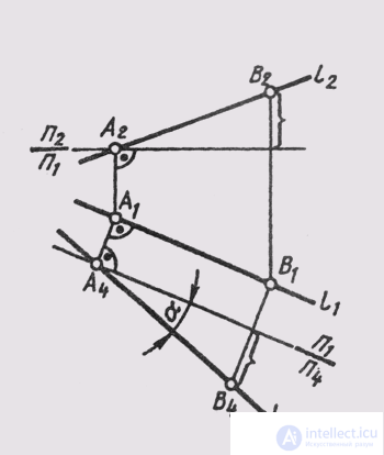
Fig. 108
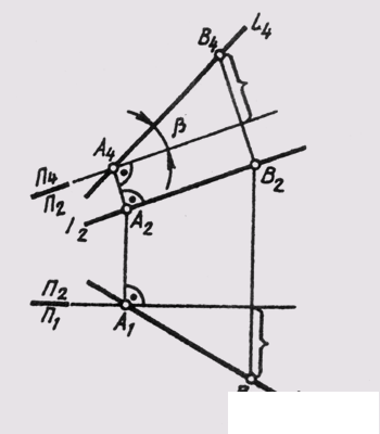
Fig. 109
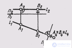
Fig. 110
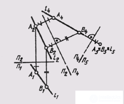
Fig. 111
perpendicular to the new axis —P 1 / P 4 parallel to the horizontal projection l 1 .
The new projection of the straight line gives the true value A 4 B 4 of the segment AB (see § 11) and allows us to determine the slope of the straight line to the horizontal plane of the projections (a = L 1 P 1 ). The angle of inclination of the straight line to the frontal plane of the projections (b = L 1 P 2 ) can be determined by plotting the image of a straight line on another additional plane P4_ | _P 2 (fig. 109).
2. Convert the drawing of a direct level so that it occupies a projection position relative to the new projection plane.
In order for the image of a straight line to be on a new projection plane (see § 10), a new projection plane should be located perpendicular to this straight level. The horizontal will have with its projection a point on the plane P 4 _ | _ P 1 . (fig. 110), and the frontal f - on P 4 _ | _ P 2
If it is required to construct a projection of a general line that is degenerate into a point, then in order to transform the drawing, two successive replacements of the projection planes will be required. In fig. 111 the original drawing of a straight line l (A, B) is transformed as follows: first, an image of a straight line is built on the plane П 4 _ | _ П 2 located parallel to the straight line l . In the system of planes П 2 _ | _ П 4 , the straight line occupied the position of the line l of the level (А 2 А 4 _ | _П 2 / П 1 ;
P 2 / P 4 || l 2 ). Then from the system P 2 _ | _ P 4 the transition is made to the system
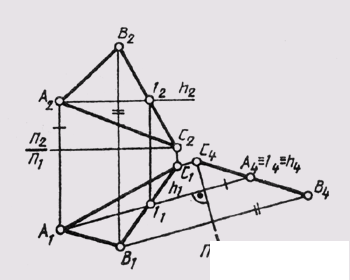
Fig. 112
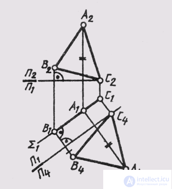
Fig. 113
P 4 _ | _P 5 , with the second new plane of projections P 5 perpendicular to the straight line l . Since the points A and B of the straight line are at the same distance from the plane P 4 , then on the plane P 5 we get the image of the straight line as a point (A 5 = B 5 = l 5 ).
3. Convert the drawing of the plane of general position so that it occupies a projection position relative to the new plane.
To solve this problem, a new plane of projections must be located perpendicular to this plane of general position and perpendicular to one of the main planes of projections. This can be done if we consider that the direction of the orthogonal projection onto a new plane of projections must coincide with the direction of the corresponding level lines of the given plane of general position. Then all the lines of this level in the new plane of the projections are represented by dots, which will give a “degenerate” plane into the direct projection (see § 47).
In fig. 112 given the construction of a new image of the plane 0 (ABC) in the system of planes P 4 _ | _P 1 . To do this, the horizontal line h (A, 1) is built in the plane 0, and the new plane of the projections P 4 is perpendicular to the horizontal h. The graphical solution of the third original problem leads to the construction of an image of a plane in the form of a straight line, the angle of inclination of which to the new projection axis P 1 / P 4 , determines the angle of inclination of the Q plane (ABC) to the horizontal projection plane (a = Q ^ P 1 ).
Having built the image of the plane of general position in the system P 2 _ | _P 4 , (P 4 to be arranged perpendicular to the front of the plane),
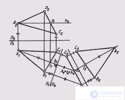
Fig. 114
You can determine the angle of inclination P of this plane to the frontal plane of the projections.
4. Convert the drawing of the projecting plane so that relative to the new plane it takes the position of the level plane.
The solution to this problem allows us to determine the value of flat figures.
A new plane of projections must be placed parallel to a given plane. If the initial position of the plane was frontally projecting, then a new image is built in the system and P 2 _ | _P 4 , and if horizontally projecting, then in the P 1 system | | P 4 . The new axis of the projections will be located parallel to the degenerate projection of the projecting plane (see § 47). In fig. 113 built a new projection A 4 B 4 C 4 of the horizontal projecting plane Sum (ABC) on the plane P 4 _ | _P 1
If in the initial position the plane occupies a general position, and you need to get an image of it as a level plane, then resort to double replacement of the projection planes, solving successively Problem 3; and then task 4. At the first replacement, the plane becomes the projecting one, and at the second - the plane of the level (Fig. 114).
Horizontal plane h (D - 1) is drawn in plane A (DEF ). With respect to the horizontal, the first axis P 1 / P 4 _ | _ h 1 is drawn . Second new axis
The projections are parallel to the degenerate projection of the plane, and the new communication lines are perpendicular to the degenerate projection of the plane. Distances for constructing projections of points on the P 5 plane should be measured on the P 1 plane from the P 1 / P 2 axis and set aside along new communication lines from the new P 4 / P 5 axis. The projection D 5 E 5 F 5 of the triangle DEF is congruent to the triangle ABC itself.
Using the method of replacing planes, it is possible to solve a number of other tasks, both independent and separate parts of tasks, including a large amount of graphic solutions.

Comments
To leave a comment
Descriptive Geometry and Engineering Graphics
Terms: Descriptive Geometry and Engineering Graphics