Lecture
According to the images of the object on the drawing judge its size and the size of its individual parts. The basis for this are the dimensional numbers, no matter what the scale and with what accuracy
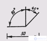
Fig. 7
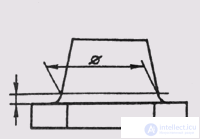
Fig. eight
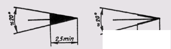
Fig. 9
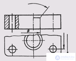
Fig. ten
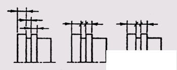
Fig. eleven
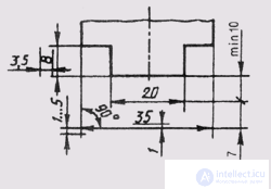
Fig. 12
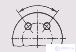
Fig. 13
completed images. Rules for applying dimensions in the drawings are established by GOST 2.307-68.
Dimensions in the drawing indicate dimensional numbers, dimension and extension lines. Dimension numbers in drawings, as a rule, indicate in millimeters without specifying the units of measurement. In cases where it is necessary to use other units of length, they are shown after the dimensional number.
Dimension numbers are applied above the dimension line, possibly closer to its middle. The gap between the dimension number and the dimension line should be about 1.0 mm. The height of the digits of dimensional numbers is not less than 3.5 mm (Fig. 7).
The dimension line is drawn parallel to the segment, the size of which is applied above it. It is carried out between the extension lines drawn perpendicular to the dimension. It is allowed to draw dimension lines directly to the lines of the visible contour, axial and center lines. In some cases, the dimension line may not be perpendicular to the extension (Fig. 8). Dimension lines limit the arrows (Fig. 9). In some cases, they are not carried out completely, but with a broken arrow on one side (Fig. 10). The size of the arrow is chosen from the thickness of the solid thick base line adopted in the drawing. Within the limits of one drawing the size of arrows should be whenever possible identical. It is not recommended to use contour, axial, center and extension lines as dimension lines.
If the length of the dimension line is small to accommodate the arrows, then the dimension line is continued beyond the extension lines, and the dimensions are applied, as shown in Fig. eleven.
Extension lines are drawn from the boundaries of the measurements, they are auxiliary and are used to place the dimension lines between them. Extension lines should, if possible, be located outside the image contour, perpendicular to the straight line segment, the size of which must be specified. Extension lines should extend beyond the ends of the dimension line arrows by 1 ... 5 mm (Fig. 12).
The minimum distance from the dimension line to the line parallel to it should be 10 mm, and between the parallel dimension lines - 7 mm.
Angular dimensions in the drawings are put in degrees, minutes and seconds, indicating the units of measurement. The size of the angle is applied above the dimension line, which is held in the form of an arc with its center at its top. Extension lines in this case are drawn radially (Fig. 13).
At different inclinations of dimension lines, dimensional numbers of linear dimensions are arranged as shown in Fig. 14, a, and angular dimensions - as shown in fig. 14, b. If the dimension line is in the zone that is shaded in the drawing, the dimensional numbers are applied on the shelves of the callout lines (Fig. 15).
If there is not enough space for writing a dimension number above the dimension line, or is this space occupied by other elements of the image and
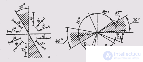
Fig. 14
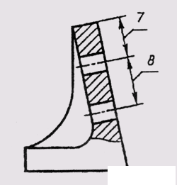
Fig. 15
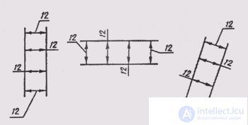
Fig. sixteen
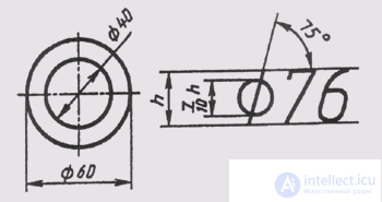
Fig. 17
It is impossible to put a dimension number into it; a dimension number is applied in one of the options shown in fig. sixteen.
In order to simplify a number of images, create convenience for reading the drawing, the standard provides for the use of symbols in the form of letters of the Latin alphabet and graphic signs, which are placed before the dimensional numbers. In the drawings apply
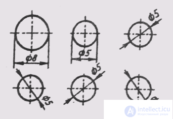
Fig. 18
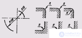
Fig. nineteen
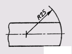
Fig. 20
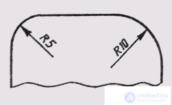
Fig. 21
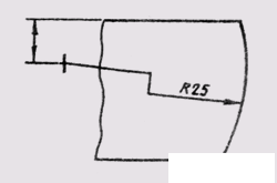
Fig. 22
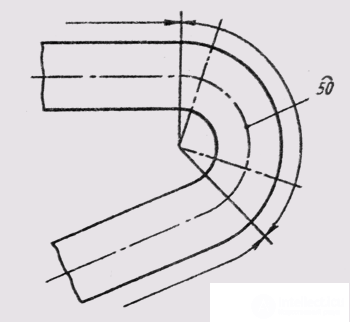
Fig. 23
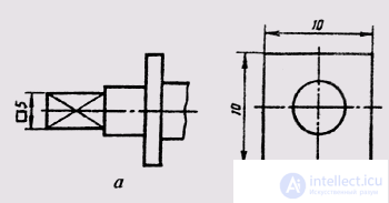
Fig. 24
signs and letters to denote the diameter and radius, the length of the arc and the square, the slope and taper, the sphere, the thickness and length of the part.
Before the size number of the diameter, the sign 0 is applied (fig. 17). Moreover, there is no gap between the sign and the number. For circles of small diameter, the dimension lines of the arrow and the size itself are applied in one of the options shown in fig. 18.
Before the size number of the radius of the arc is always put a sign in the form of a capital Latin letter R. In this case, the dimension line is drawn towards the center of the arc and is limited to only one arrow that runs into the arc or its continuation (Fig. 19). If the radius on the drawing is less than 6 mm, the arrow is recommended to
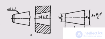
Fig. 25
lay on the outside of the arc. If it is necessary to set the position of the center of the arc, it is marked by the intersection of the center or extension lines (Fig. 20). In those cases when the drawing shows an arc of a large radius, for which the center can not be indicated, the dimension line is cut off, not reaching the center (Fig. 21). If in this case the center should be noted, it is allowed to bring it closer to the arc (Fig. 22). The dimension line in this case is shown with a break of 90 °, and both sections of the dimension line are held in parallel. You should not place on one straight dimension lines that extend from one center and are intended to indicate dimensional arcs. Radiating is recommended to designate arcs up to 180 °; arcs whose magnitude is greater than 180 ° are denoted by diameter.
The arc sign is applied above the dimension number (fig. 23). The length of the arc is given in linear units, and the dimension number indicating the arc is drawn over the dimension line in accordance with the usual requirements.
For setting the dimensions of a square, the corresponding sign D is used, whose height is equal to 7/10 of the height of the dimensional number (Fig. 24a ). If the square is otherwise located, the dimensions of its sides are applied (Fig. 24, b). It should be noted that the sign of the square is applied only on the image in which it is projected in a line.
The sign of the surface taper is applied on the shelf of the leader line, which is located parallel to the axis of the cone or on the axis of the cone (Fig. 25a ). The taper sign is positioned so that its acute angle is directed toward the apex of the cone. The size of the taper is determined by the ratio of the difference between the diameters of two cross sections of the cone and the distance between these sections, i.e. k = D - dll, where D is the diameter of a large section; d is the diameter of a smaller section; l is the distance between sections. The taper is indicated as a simple fractional number (Fig. 25, b).
The sign of the slope of a straight line indicate the shelf line-callouts. Slope i is the tangent of an angle between a given straight line and a horizontal or vertical straight line (Fig. 26a). Slope sign is located
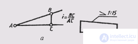
Fig. 26
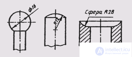
Fig. 27
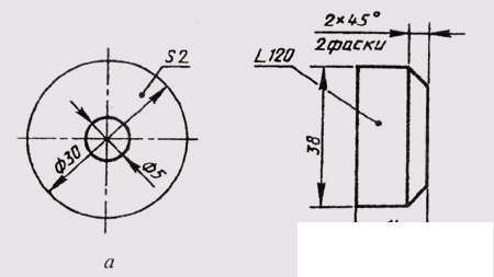
Fig. 28
so that its acute angle was directed towards the slope of a straight line (Fig. 26, b). The slope, like taper, in the drawing is set with a simple fraction, as a percentage or in ppm.
To designate a sphere in the drawing, use the sign of diameter or radius. In cases where the sphere is difficult to distinguish from other surfaces from a drawing, the word “Sphere” may be added before the sign of the radius or diameter. The inscription on the drawing is carried out according to the type “Sphere diameter 17” or “Sphere R 10” (Fig. 27).
Simple flat parts are depicted as a single projection. In these cases, its thickness is indicated by the lowercase letter s and the inscription on the drawing is carried out according to the type s2 and is located on the shelf of the leader line (Fig. 28, a). The length of the subject indicate the letter / (Fig. 28, b).
Chamfers in the drawings are applied in two linear dimensions (Fig. 29, a) or one linear and one angular (Fig. 29, b). In case if
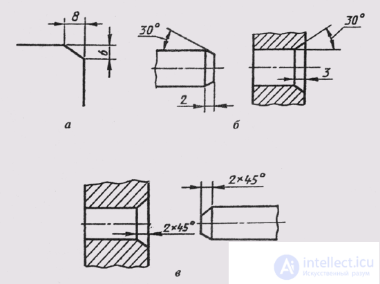
Fig. 29
the angle of inclination of the generatrix of the cone is 45 °; simplified chamfering is used when the dimension line is drawn parallel to the axis of the cone, and the inscription is of the type “2 x 45” (Fig. 29, c).

Comments
To leave a comment
Descriptive Geometry and Engineering Graphics
Terms: Descriptive Geometry and Engineering Graphics