Lecture
COMPOSITION DRAWING
The components of the composition:
The position of the main beam
Point of view distance (angle of view)
Horizon position
The position of the main beam depends on the composition of the object:
a) when a symmetrical composition of the beam is recommended to carry through the middle of the object
b) with a greater development of one of the parts of the composition, the beam shifts closer to this part
The location of the main beam outside the middle third of the line of sight
not allowed
The prospect of direct private position
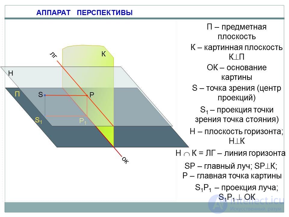
DEVICE PERSPECTIVES
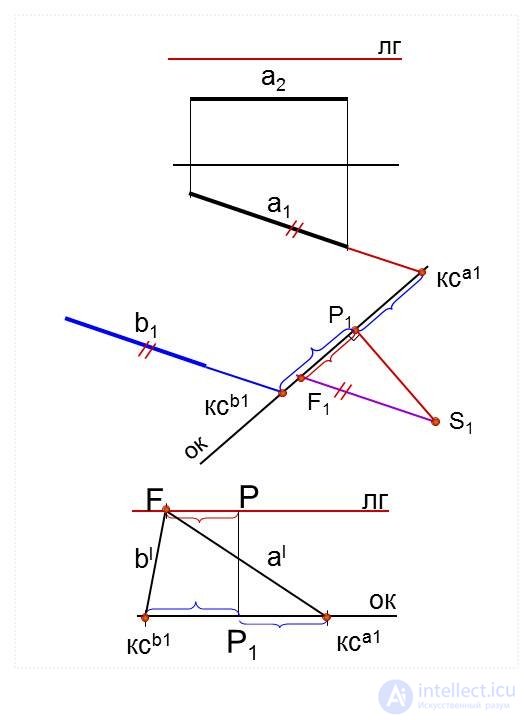
Perspective of horizontal lines
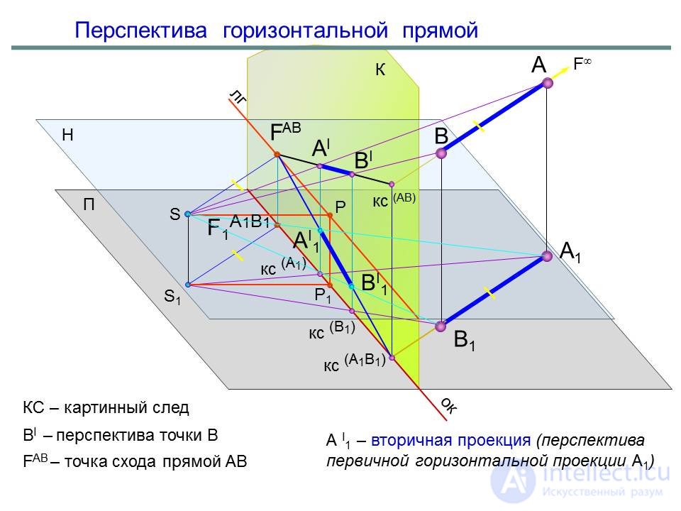
Horizontal lines have a vanishing point on the horizon line.
The perspective of horizontal lines is built on two points:
1 - picture trail - the point of intersection of the line with the picture K;
2 - the vanishing point of the line - the point of intersection with the picture K of the beam from S, parallel to this line
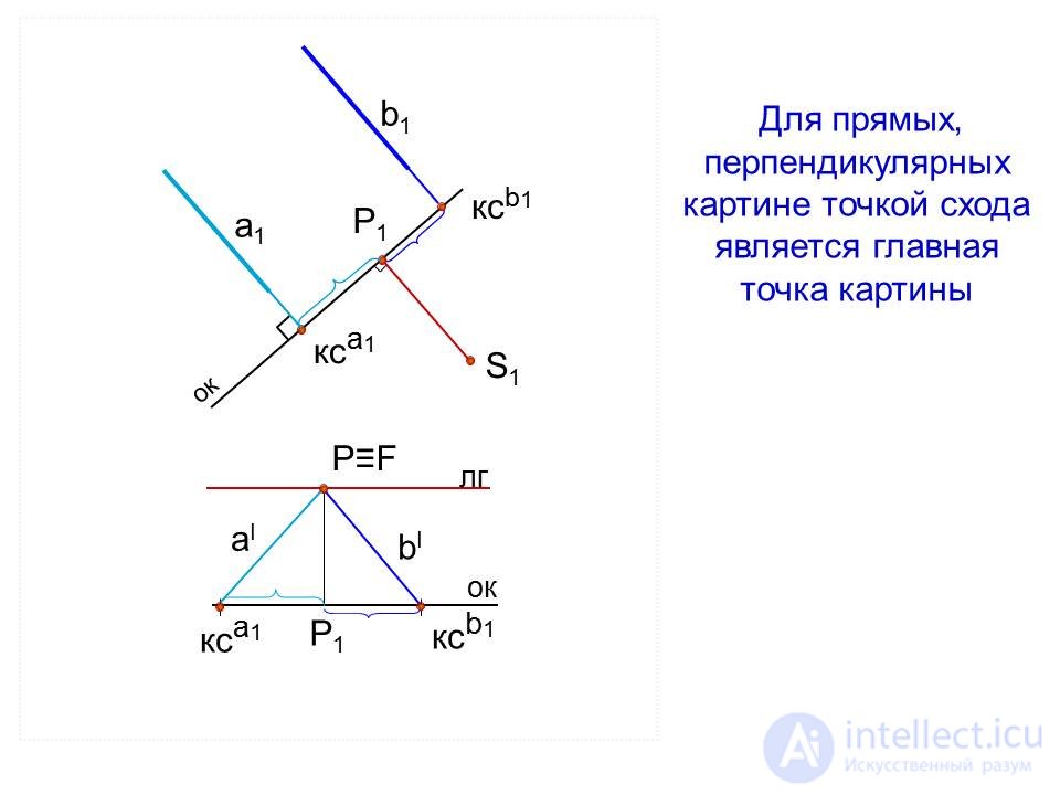
Perspective straight, perpendicular to the picture
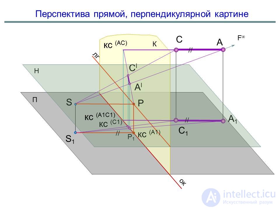
For straight, perpendicular to the picture, the vanishing point is the main point of the picture.
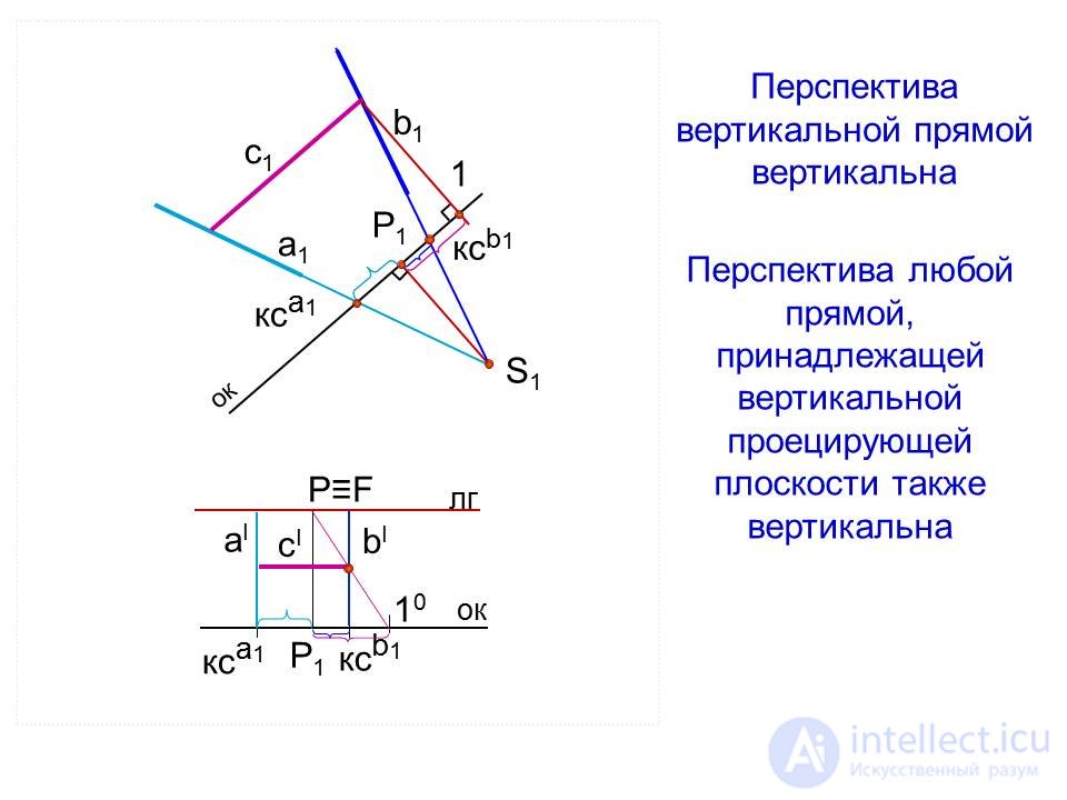
The perspective of a vertical line, and a straight line lying in a vertical plane.
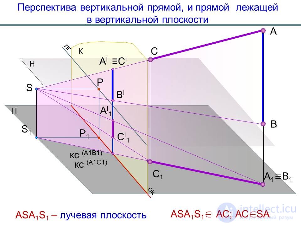
Perspective vertical straight vertical
The perspective of any straight line belonging to the vertical projecting plane is also vertical.
Perspective of direct general position
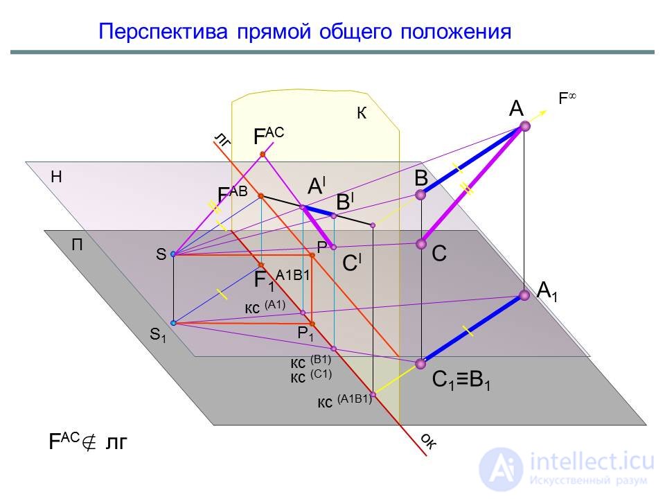
A bundle of parallel general straight lines has a common vanishing point of straight lines in perspective.
The vanishing point of lines of general position in the future does not lie on the horizon line.
Selection of the angle of view
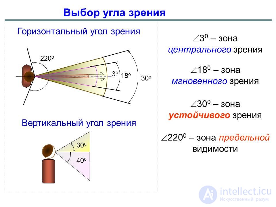
At the beginning of the manual, the definition of the term “prospect” referred to the need to observe certain conditions that limit the mutual position of a point of view, picture and object. These restrictions depend on the characteristics of our vision and make up the concept of "choice of point of view." The correct "choice" is of great artistic and artistic value. Efficiency, clarity and, most importantly, perceptual image perception accuracy are highly dependent on it.
 |
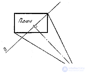
The choice of the point of view is based on the rule: "the relative position of the object being depicted, the point of view and the picture plane must be such that this object is completely inside such a circular cone whose vertex coincides with the point of view, the axis is perpendicular to the picture plane and the diameter of the base circle is picture fits in the height of the cone from one to three times. At the same time  between the forming cone at the vertex will vary from 53 ° to 18 °. At an angle of 28 °, the diameter of the base circle is placed twice in height. On the plane P 1 (Fig. 20) angle projected into a corner between the straight lines drawn through the base S 1 of the point of view S and the extreme points of the plan of the imaged object; the height of the cone is projected on the bisector of this angle. As a rule, the base S 1 P 1 of the main beam SP coincides with the bisector of the angle . The base of the picture O is located perpendicular to the bisector.
 |
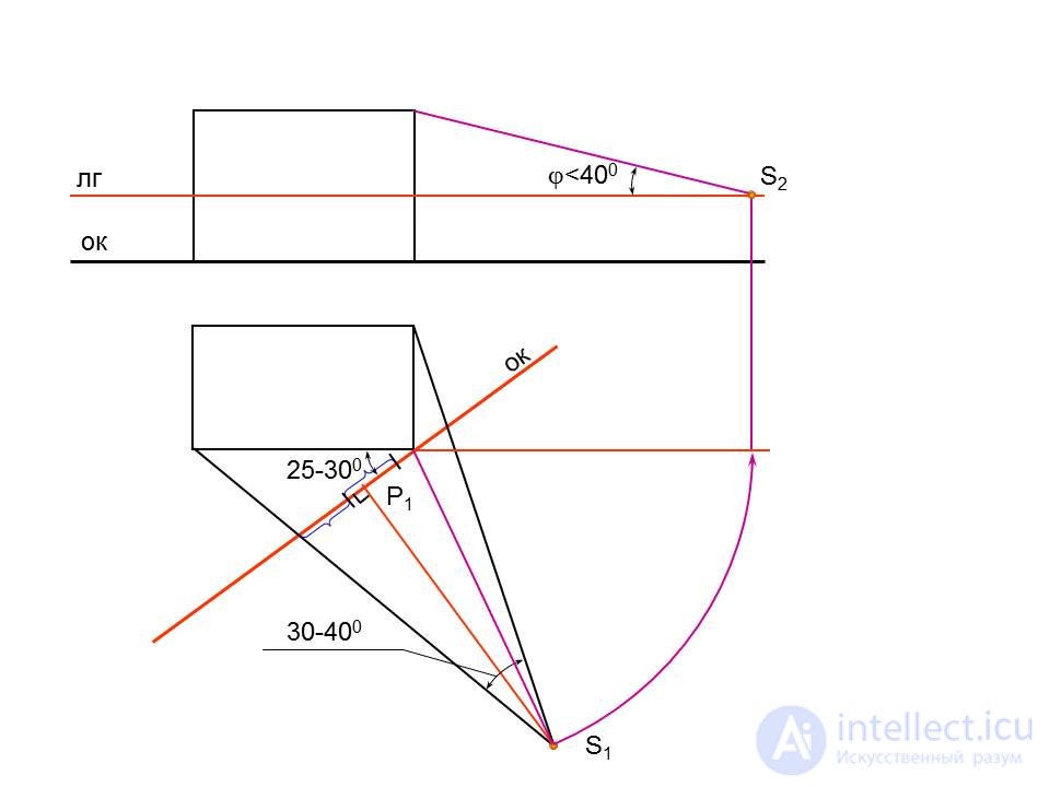
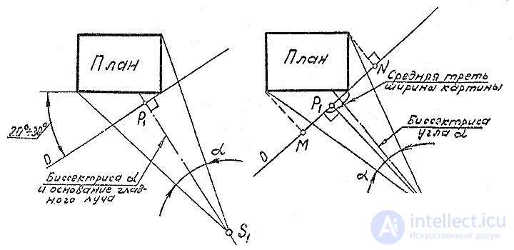
In some cases, depending on the shape of the object, the bisector of the angle and the base of the main beam. But, at the same time, it is necessary that the point P 1 be in the middle third of the width of the picture MN (Fig. 21). The base of the picture should be perpendicular to S 1 P 1 .. When choosing the point of view S (S 1 ), in addition to providing the best angle of view (28 °), the main and side facades of the building or structure should be shown in perspective. This is possible if the points of view of S (S 1 ) are arranged as shown in Fig. 20, 21, 23. At the same time, a so-called perspective is obtained. The optimum angle of inclination of the picture to the plane of the main facade is in the range of 20 - 30 °. Angular perspective is used to build an image of a separate building or structure.
If the point of view is located as shown in Fig. 22, the perspective is called frontal and is used to build images of streets and squares.
The distance of the point of view to the subject plane SS 1 = 1.7 m (perspective with a normal height of the horizon).
There are: a “bird's-eye” perspective - the height of the point of view is up to 100 m and more;
perspective from below - the point of view is chosen below the subject plane. In fig. 23 shows the perspectives of one object at four different heights of the horizon (H 1 , H 2 , H 3 , H 4 ) .
In practice, the position of the point S on the plan is chosen as follows: 1. A clearance with an angle of 28 ° is cut out on a cardboard sheet or a transparent triangle with an angle of 30 ° is taken. Putting it on the sheet, positioning so that the sides of the template pass through the extreme points of the plan, mark the top of the corner S 1 at the top of the angle point of view S and hold through the point S 1 and the extreme points of the plan straight lines.
2. Through the point S 1 spend the bisector of the angle which will simultaneously be the base of the main beam.
3. Through the angle of the building closest to the point of view, the base of the picture plane is perpendicular to the angle bisector and mark the base P 1 of the main point P (P 1 = O  S 1 P 1 ) . If the angle between the picture plane and the plane of the main facade will go beyond 20-30 °, you should repeat the construction by changing the position of point S 1 .
 |
Another remark regarding the choice of the position of the picture plane.
A picture can occupy three positions:
a) be between the viewer and the object;
b) cross the object;
c) be behind the object.
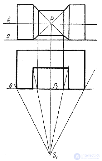
The first position is the most commonly used, but a perspective image, thus it turns out to be reduced in size, so it’s recommended to cross the object in the picture plane (on the subject plane the base of the picture O crosses the floor plan) (Fig. 24).
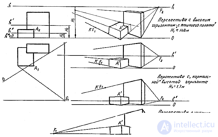 |
Fig. 23
1. The way of architects . This method is based on the property of perspective projections of parallel lines, which is that they converge at one point (they have a common vanishing point F ).
2. The radial method consists in the fact that the perspective of any point is defined as the trace of the line of sight (ie, as the point of intersection of the line of sight passing through a given point with the picture plane). The method was developed by German artist, mathematician and engraver Albert Dürer (1471 - 1528) and therefore is sometimes called Dürer's method .
3. Mesh method . The method of constructing a perspective using a grid is that a uniform orthogonal grid is applied on orthogonal projections and then a perspective image of this grid is built.

Comments