Lecture
The properties of a three-projection drawing of a point make it possible to build a third projection onto other planes, introduced instead of the given, along horizontal and frontal projections.
In fig. 65, and the point A and its projections are shown - horizontal А 1 and frontal А 2 . According to the conditions of the task, it is necessary to replace the planes P 2 . The new projection plane is denoted by P 4 and placed perpendicular to P 1 . At the intersection of the planes P 1 and P 4 we get a new axis P 1 / P 4 . A new projection of point А 4 will be located on communication lines passing through point А 1 and perpendicular to the axis П 1 / П 4 .
Since the new plane P 4 replaces the frontal plane of the projection P 2 , the height of point A is depicted equally in full size both on the plane P 2 and on the plane P 4 .
This circumstance allows us to determine the position of the projection A 4 , in the system of planes P 1 _ | _ P 4 (Fig. 65, b) in the complex drawing. To do this, it is sufficient to measure the height of a point on the replaced plane.
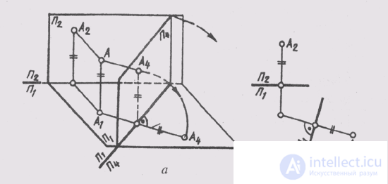
Fig. 65
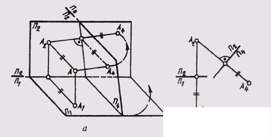
Fig. 66
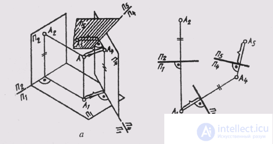
Fig. 67
ST 2 , put it on a new communication line from a new axis of projections - and a new projection of point А 4 will be built.
If a new projection plane is introduced instead of the horizontal projection plane, i.e., P 4 _ | _ P 2 (Fig. 66a ), then in the new system of planes the new projection of the point will be on the same communication line with the front projection, moreover A 2 And 4 _ | _. In this case, the depth of the point is the same both on the plane P 1 and on the plane P 4 . On this basis, А 4 is built (Fig. 66, b) on the А 2 А 4 communication line at such a distance from the new axis П 1 / П 4 on which А 1 is located from the axis П 2 / П 1 .
As already noted, the construction of new additional projections is always associated with specific tasks. In the future, a number of metric and positional problems will be considered, solved using the method of replacing projection planes. In problems where the introduction of one additional plane does not give the desired result, one more additional plane is introduced, which is designated as P 5 . It is placed perpendicular to the already introduced plane P 4 (Fig. 67, a), i.e. P 5 P 4 and produce a construction similar to the previously discussed. Now the distances are measured on the replaceable second of the main projection planes (in Fig. 67, b on the P 1 plane ) and lay them on the new A 4 A 5 communication line , from the new projection axis P 5 / P 4 . In the new system of planes P 4 P 5 get a new two-projection drawing, consisting of orthogonal projections A 4 and A 5 , connected by a communication line
A 4 A 5 _ | _P 4 / P 5

Comments
To leave a comment
Descriptive Geometry and Engineering Graphics
Terms: Descriptive Geometry and Engineering Graphics