Lecture
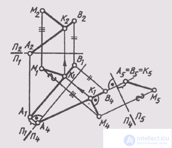
Some distance determination tasks were discussed in previous sections. For example, in § 42 the actual value of a straight line segment was determined by the triangle method, in § 57 the real value of a segment was determined by the method of plane-parallel transfer. This task can also be solved by a method of replacing projection planes (see § 58) or by a method of rotation (see § 59). Determining the length of a straight line segment allows you to solve the problem of determining the distance from a point to a point, since this distance is determined by a straight line segment. The distance from a point to a straight line is measured by a perpendicular segment drawn from a point to a straight line. A segment of this perpendicular is depicted full-scale on the plane if it is drawn to the projecting line. It means that it is necessary to transform the drawing of this straight line, making it in the new system of projection planes projecting (see § 58, problem 2). In fig. 140 distance from point M to straight line AB is defined :
1) P 2 _ | _P 1 -> P 1 _ | _P 4 , P 4 || AB, P 1 / P 4 || A 1 B 1 ;
2) P 1 P 4 -> P 4 _ | _P 5 , P 5 _ | _ AB, P 4 / P 5 _ | _A 4 B 4 ;
3) M 5 K 5 is the true distance from point M to line AB;
4) in order to construct the projections of the perpendicular MK in the original system of planes, build the base of the perpendicular, point K — on the line AB from the condition that in system P 4 _ | _P 5 ; it occupies the position of a level line, i.e.
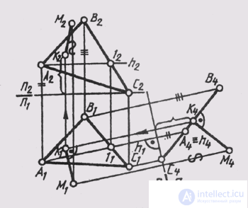
M 4 K 4 _ | _A 4 B 4 . The horizontal and frontal projections of the point K are determined by lines from the condition that its line AB belongs . The distance from the point to the plane is measured by the perpendicular segment, lowered from point to plane. Since the perpendicular to the projecting plane is a level line, it is convenient to have a “degenerate” projection of the given plane in the drawing, that is, to transform the drawing (see § 58, problem 3). In fig. 141 the projections of the perpendicular MK are constructed , the segment of which determines the distance from the point M to the plane Q (ABC):

Fig. 140
1) P 1 , P 2 -> P 1 _ | _P 4 , P 4 _ | _Q, P 1 / P 4 _ | _ h (A, 1) ~ 0;
2) M 4 K 4 _ | _Q 4 - the true value of the distance from the point M to the plane Q;
3) M 1 K 1 _ | _K 4 K l or || P 1 / P 4 ;
4) K 2 built using the height of the point K, measured on the plane P 4 .
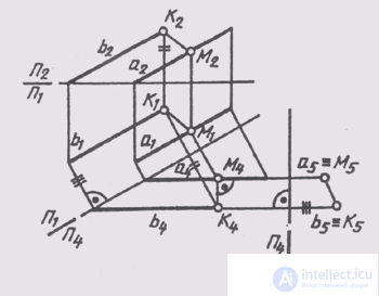
The distance between parallel straight lines is measured by the perpendicular segment between them. In fig. 142 the distance between straight lines a and b is determined by converting the drawing of straight lines. First built

Fig. 141
the image of lines on the plane P 4 _ | _P 1 . In this system of planes, straight lines occupy the position of the level line:
a (b) || P 4 ; P 1 / P 4 || a, (b 1 ).
In the system of planes П 4 _ | _ П 5 straight lines occupy projecting with respect to the plane Пз

Fig. 142
tion: P 5 _ | _ a (b); P 4 / P 5 _ | _a (b 4 ) Section M 5 K 5 between degenerate projections of straight lines determines the true value of the distance between the lines a and b. The constructions of the projections of the perpendicular MK in the original system of projection planes are similar to those considered earlier.
To determine the distance between crossed lines, it is necessary to make one of the lines projecting in the new system of planes of projections.
The distance from a straight line to a plane parallel to the straight line is measured by the perpendicular segment, lowered from any point of the straight line to the plane. It means that it is enough to transform a generic plane into the position of a projecting plane, take a point on a straight line, and the solution of the problem will be reduced to determining the distance from the point to the plane.
The distance between parallel planes is measured by the segment of the perpendicular between them, which is easily constructed if the planes occupy a projection position in the new system of projection planes, that is, the third initial task of transforming the drawing is again used.
Comments
To leave a comment
Descriptive Geometry and Engineering Graphics
Terms: Descriptive Geometry and Engineering Graphics