Lecture
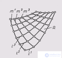
The surface is called the set of consecutive positions of lines moving in space. This line can be straight or curved and is called the surface generator . If forming a curve, it can have a constant or variable form. Moving generators along guides, which are lines of a different direction than generators. Guide lines define the law of displacement. When the generator moves along guides, a surface frame is created (Fig. 84), which is a combination of several successive positions of the generators and guides. Considering the skeleton, one can make sure that the generators of l and the guides of t can be swapped, but the surface is the same.
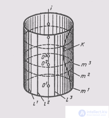
Any surface can be obtained in various ways. Thus, a straight circular cylinder (Fig. 85) can be created by rotating the generator l around the z axis parallel to it. The same cylinder is formed

Fig. 84

Fig. 85
moving the circle m with the center at the point O, sliding along the axis i . Any curve k lying on the surface of the cylinder forms this surface during its rotation around the axis '/'.
In practice, of all possible ways of forming a surface, the most simple is chosen.
Depending on the shape of the generatrix, all surfaces can be divided into ruled ones, in which a straight line is forming, and non-ruled ones, in which the forming line is.
In ruled surfaces, there are surfaces that develop, develop, combine with all their points with the plane without gaps and folds, and non-developable, which cannot be combined with the plane without breaks and folds.
Surfaces of all polyhedra, cylindrical, conical and torso surfaces are considered to be developable surfaces. All other surfaces are non-rolling. Nonlinear surfaces can be with a generator of constant shape (surfaces of revolution and tubular surfaces) and with a generator of variable shape (channel and frame surfaces).
To define surfaces, a set of independent geometrical conditions is chosen that uniquely defines a given surface in space. This set of conditions is called a surface determinant. The determinant consists of two parts: geometric, which includes the main geometric elements and the relations between them, and algorithmic, containing the sequence and nature of the operations of transition from basic constant elements and quantities to variable elements of the surface, i.e. the law of constructing individual points and lines of surface.

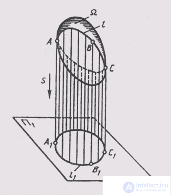
Fig. 86

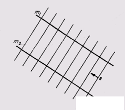
Fig. 87
The surface in the complex drawing is defined by the projections of the geometric part of its determinant, indicating the method of constructing its components. In the surface drawing, for any point in space, the question of whether it belongs to a given surface is unambiguously solved. The graphical task of the elements of the surface determinant ensures the reversibility of the drawing, but does not make it vivid. For clarity, they resort to building projections of a sufficiently dense framework of generators and to constructing outline lines of the surface (Fig. 86). When projecting the surface Q on the plane of the projections, the projecting rays touch this surface at points that form on it a certain line l , which is called a contour line. The projection of the contour line is called the outline of the surface. On the complex drawing, any surface has: on P 1 - a horizontal essay, on P 2 - a frontal essay, on P 3 - a profile essay of the surface. The essay includes, in addition to the projections of the contour line, also projections of crop lines.
From a significant set of surfaces in the course of engineering graphics, all developable surfaces will be considered, which include face, conical, cylindrical, torso surfaces, some surfaces of rotation and helical.
The simplest surface commonly used in engineering graphics is the plane, which is a surface formed by moving a straight line generator (Fig. 87) along two parallel or intersecting straight lines m 1 and m 2 .
Comments
To leave a comment
Descriptive Geometry and Engineering Graphics
Terms: Descriptive Geometry and Engineering Graphics