Lecture
To build an image of an object, at first, its individual elements are depicted as the simplest elements of space. So, depicting a geometric body, one should construct its vertices, represented by dots; edges represented by straight and curved lines; faces represented by planes, etc.
The rules for constructing images on engineering drawings are based on the projection method. A single image (projection) of a geometric body does not allow one to judge its geometric shape or the shape of the simplest geometrical images that make up this image. Thus, it is impossible to judge the position of a point in space by its one projection; its position in space is determined by two projections.
Consider an example of constructing the projection of a point A located in the space of a dihedral angle (Fig. 60). We place one of the projection planes horizontally, let's call it the horizontal plane of the projections and denote it with the letter П 1 . Projection elements
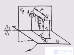
Fig. 60
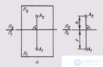
Fig. 61
the spaces on it will be denoted with the index 1: A 1 , and 1 , S 1 ... and called horizontal projections (points, straight lines, planes).
Let's place the second plane vertically in front of the observer, perpendicular to the first one, let's call it the vertical plane of the projections and denote P 2 . The projections of the elements of space on it will be denoted with the index 2: А 2 , 2 , S 2 and called frontal projections (points, straight lines, planes). The line of intersection of the planes of the projections is called the axis of the projections.
We project the point A orthogonally on both planes of the projections:
AA 1 _ | _ P 1 ; AA 1 ^ P 1 = A 1 ;
AA 2 _ | _ P 2 ; AA 2 ^ P 2 = A 2 ;
The projection rays AA 1 and AA 2 are mutually perpendicular and create in space the projecting plane AA 1 AA 2 , perpendicular to both sides of the projections. This plane intersects the planes of projections along the lines passing through the projections of point A.
To get a flat drawing, let's combine the horizontal plane of the projections P 1 with the front plane P 2 by rotating around the axis P 2 / P 1 (Fig. 61, a). Then both projections of the point will be on the same line, perpendicular to the axis P 2 / P 1 . The straight line А 1 А 2 connecting the horizontal А 1 and frontal А 2 projections of a point is called the vertical line of communication.
The resulting flat drawing is called a complex drawing. It represents the image of the object on several planes combined. A complex drawing consisting of two orthogonal projections interconnected is called a two-projection. In this drawing, the horizontal and frontal projections of a point always lie on the same vertical communication line.
Two interconnected orthogonal projections of a point uniquely determine its position relative to the planes of the projections. If we determine the position of point a relative to these planes (Fig. 61, b) by its height h (AA 1 = h) and depth f (AA 2 = f ), then these values in the complex drawing exist as segments of the vertical link. This circumstance makes it easy to reconstruct the drawing, i.e., determine the position of a point relative to the planes of projections from the drawing. To do this, it is enough to restore perpendicular to the plane of the drawing at the point A 2 of the drawing (assuming it is frontal) with a length equal to the depth f . The end of this perpendicular will determine the position of point A relative to the plane of the drawing.

Comments
To leave a comment
Descriptive Geometry and Engineering Graphics
Terms: Descriptive Geometry and Engineering Graphics