Lecture
The image of the visible part of the object surface facing the observer is called a view.
According to the content and nature of the implementation of the species are divided into basic, additional and local.
GOST 2.305—68 establishes the following name for the main species obtained on the main planes of the projections (see fig. 165): 7 — front view (main view); 2 - top view; 3 - left view;
4 - right side view; 5 is a bottom view; b - rear view. In practice, three types are more widely used: front view, top view and left view.
The main types are usually located in a projection relationship among themselves. In this case, the name of the species in the drawing is not necessary to inscribe.
If any view is displaced relative to the main image, its projection connection with the main view is broken, then an inscription of type “A” is performed on this view (Fig. 166).
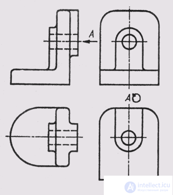
Fig. 166
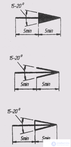
Fig. 167
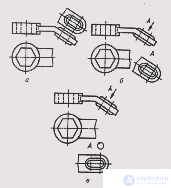
Fig. 168
The gaze direction should be indicated by an arrow indicated by the same capital letter of the Russian alphabet as in the inscription above the view. The ratio of the sizes of the arrows indicating the direction of gaze should correspond to those shown in fig. 167.
If the views are in a projection connection between each other, but are separated by any images or are not located on one sheet, then they are also labeled “A” on top of them.
An additional view is obtained by projecting an object or a part of it onto an additional plane of projections not parallel to the main planes (Fig. 168). This image must be performed in the case when any part of the object is not shown without distorting the shape or size on the main planes of the projections. The additional projection plane in this case can be located perpendicular to one of the main projection planes.
When the additional view is located in direct projection connection with the corresponding main view, it is not necessary to designate it (Fig. 168, a). In other cases, the additional view should be marked on the drawing with an “A” type inscription (fig. 168, b), while
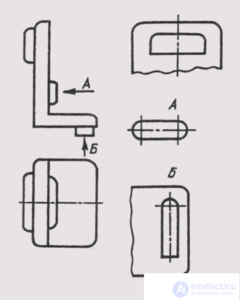
Fig. 169
For an additional image type, you need to put an arrow indicating the direction of the sight, with the appropriate letter designation.
The additional view can be rotated while maintaining the position adopted for the item in the main image. At the same time to the inscription you need to add a sign (Fig. 168, c).
Local view is called the image of a separate, limited place of the surface of the object (Fig. 169).
If the local view is located in direct projection connection with the corresponding images, then it is not designated. In other cases, local species are designated like additional species, the local species may be limited by a cliff line (“B” in Fig. 169).

Comments
To leave a comment
Descriptive Geometry and Engineering Graphics
Terms: Descriptive Geometry and Engineering Graphics