Lecture
A detail is a product made from a metal that is uniform in name and grade, without the use of assembly operations. Examples of parts can be a roller made of one piece of metal, a bolt, a key, etc.
For the manufacture of each part you need its working drawing. The working drawing of the part is a document containing the image of the part, dimensions and other data necessary for the manufacture, repair and control of the part. This document contains data on the material, surface roughness, technical requirements, etc. Thus, the working drawing includes both a graphic and a text part.
When a working drawing is executed, the details determine the view that gives the most understanding of its structure (main view), and the necessary number of other views and images.
Select the desired paper size and set an acceptable image scale. Next, perform the layout of the drawing, ie, proceed to the rational placement of images on the sheet. Outline drawing frame and title block. If the details are shown that require the application of tables of parameters, for them provide a place in the upper right of the format. For other parts on the right, they leave space for recording technical requirements for them, including information on the hardness of the metal, deviations of the axis of alignment, curvature radii, etc. Further, outlines the rectangles in size corresponding to the overall dimensions of the images; at the same time leave the necessary margin of space for the application of dimensions around each image. In the upper right corner leave space for the application of signs of roughness.
The inscriptions on the drawings in the specifications and tables are performed in accordance with GOST 2.316-68. The text part, the inscriptions and the tables are included in the drawing, when the data contained in them cannot be expressed graphically or conventions. The text of the inscription should be accurate, short and parallel to the main inscription of the drawing. The heading "Technical Requirements" is written. The items of the technical requirements should be numbered and grouped according to their nature in accordance with the recommendations of GOST 2.316-68.
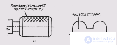
Fig. 263
The inscriptions relating to the image may contain no more than two lines located above and below the leader-line shelf (Fig. 263, a). Leader-line is ended either with a point on the image, or with an arrow (fig. 263, b).
The main inscription is carried out in accordance with GOST 2.1 04 —68 and 2.107-68 “Basic requirements for working drawings”. The name of the parts is written down in the nominative case in the singular in the names consisting of several words; in the first place the noun is placed, for example: “Cogwheel”.

Comments