Lecture
To determine the position of a geometric body in space and to obtain additional information on their images, it may be necessary to construct a third projection. Then the third plane of the projections is placed to the right of the observer perpendicularly simultaneously to the horizontal plane of the projections P 1 and the frontal plane of the projections P 2 (Fig. 62, a). As a result of the intersection of the front P 2 and profile P 3 planes of projections, we obtain a new axis P 2 / P 3 , which is located on the complex drawing parallel to the vertical communication line A 1 A 2 (Fig. 62, b). The third projection of point A , the profile one, turns out to be connected with the frontal projection A 2 by a new communication line, which is called horizontal
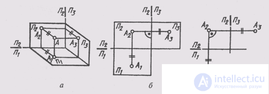
Fig. 62
Noah. Front and profile projections of a point always lie on the same horizontal communication line. Moreover, A 1 A 2 _ | _ A 2 A 1 and A 2 A 3 , _ | _ P 2 / P 3 .
The position of a point in space in this case is characterized by its latitude — the distance from it to the profile plane of the projections P 3 , which we denote by the letter p.
The resulting complex point drawing is called three-projection.
In a three-projection drawing, the depth of the AA 2 point is projected without distortion on the planes P 1 and P 2 (Fig. 62a ). This circumstance allows us to construct a third - frontal projection of point A along its horizontal А 1 and frontal А 2 projections (Fig. 62, c). To do this, through the frontal projection of the point you need to draw a horizontal communication line A 2 A 3 _ | _A 2 A 1 . Then, in any place on the drawing, draw the axis of the projections П 2 / П 3 _ | _ А 2 А 3 , measure the depth f of the point on the horizontal projection field and put it on a horizontal communication line from the axis of the projections P 2 / P 3 . Get the profile projection A 3 points A.
Thus, in the complex drawing, consisting of three orthogonal projections of a point, two projections are on the same communication line; communication lines are perpendicular to the respective axes of the projections; two projections of a point completely determine the position of its third projection.
It should be noted that in complex drawings, as a rule, the planes of projections are not limited and their position is set by the axes (Fig. 62, c). In cases where the conditions of the task do not require
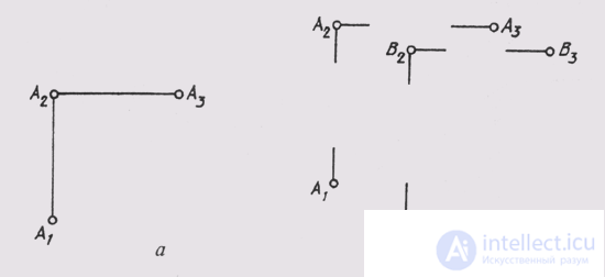
Fig. 63
This means that the projections of points can be given without an image of the axes (Fig. 63, a, b). Such a system is called baseless. Communication lines can also be conducted with a gap (Fig. 63, b).

Comments