Lecture
In those cases when it is necessary to quickly explain the shape of the subject in question, show it clearly, use a technical drawing. A technical drawing is a visual image of an existing or projected object, made without the use of drawing tools, by hand on an eye scale with respect for the proportions and sizes of the elements making it up. Technical drawings used in design practice, are used in order to more quickly express their thoughts in visual form. This makes it possible to more clearly, clearly explain the drawings of complex objects. The use of technical drawing allows you to consolidate a technical idea or suggestion. In addition, the use of a technical drawing of a detail is very useful when sketching parts from life, although it is possible to carry out a technical drawing according to the complex drawing of the object.
The most important requirement for the technical drawing is visibility. A technical drawing in finished form with shadow and hatching can sometimes be more visual than an axonometric image and with its dimensions can replace a drawing of a simple part that serves as a document for its manufacture.
In order to quickly and correctly execute a technical drawing, it is necessary to acquire skills in drawing parallel lines under different inclinations, at different distances, of different thickness without using drawing tools, without using devices, divide the segments into equal parts, build the most used angles (7.15, 30 , 41,45,60,90 °), divide the angles into equal parts, build circles, ovals, etc. It is necessary to have an idea about the image of various figures in each of the projection planes, to be able to perform images on the technical drawing and more than used flat shapes and simple geometric shapes.
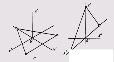
Fig. 297
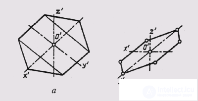
Fig. 298
Before starting the execution of a technical drawing, the question of choosing the most effective system of a visual image is decided. In machine-drawing, rectangular isometry is most often used for this purpose. This is explained by the fact that the outlines of figures located in axonometric planes undergo the same distortion in isometry, which ensures the visibility of the image and the relative simplicity of its achievement. Rectangular dimetry is also used.
In fig. 297, a technical drawing of a rectangular triangle located in the horizontal plane of the projections and made in rectangular isomerism is shown, and in fig. 297, b - technical drawing of a rectangular triangle located in the frontal plane of the projections and made in rectangular dimetry.
In fig. 298, and shows a technical drawing of a hexagon located in the horizontal plane of the projections and made in a rectangular isometry. In fig. 298, b is a technical drawing of the same hexagon, made in rectangular dimetry. Similarly, a drawing of a circle located in
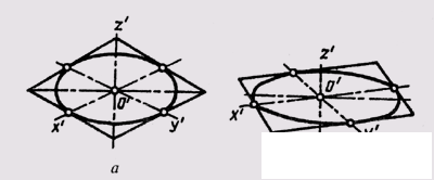
Fig. 299
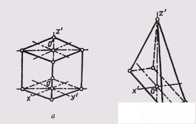
Fig. 300
the horizontal plane of the projections (Fig. 299, a), and a technical drawing of the same circle, located in the frontal plane of the projections and made using the rules of rectangular diameter (Fig. 299, b).
Using the rules for constructing axonometric projections and technical drawings of the simplest flat figures, one can proceed to the technical drawings of three-dimensional geometric figures.
In fig. 300, and a technical drawing of a straight tetrahedral pyramid, shown in rectangular isomerism, is shown in fig. 300, b - technical drawing of a straight tetrahedral pyramid, made in rectangular dimetry.
Performing technical drawings of surfaces of revolution associated with the construction of ellipses. In fig. 301, and a technical drawing of a straight circular cylinder, made in rectangular isomerism, is shown, and in fig. 301, b - drawing of a straight circular cone, made in rectangular dimetry.
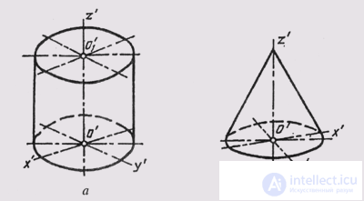
Fig. 301
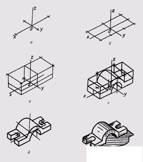
Fig. 302
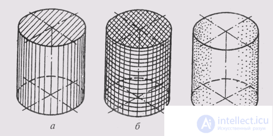
Fig. 303
Then you can begin to build more complex forms of technical details.
Technical drawing can be made in this sequence.
1. In the place selected on the drawing, axonometric axes are constructed and the part is planned to be located taking into account its maximum visibility (Fig. 302, a).
2. Mark the overall dimensions of the part, starting from the base, and build a volumetric parallelepiped, covering the entire part (Fig. 302, b).
3. The dimensional parallelepiped is mentally divided into separate geometric forms that make it up, and they are distinguished by their thin lines (Fig. 302, c).
4. After checking and clarifying the correctness of the blueprints made, the visible elements of the part are circled with lines of the required thickness (Fig. 302, d, e).
5. Choose a shading method and perform the corresponding drawing of the technical drawing (fig. 302, e). In fig. 302 shows the sequence of the technical drawing of the teteli.
To increase clarity and expressiveness, a technical hatching is applied to hatching with solid parallel lines of various thickness or hatching in the form of a grid. Drawing on a technical drawing of light and shade, showing the distribution of light on the surfaces of the imaged object, is called shading. Shading can also be done with dots. With increasing illumination, the distance between points increases. When shading is performed, it is considered that the light to be imaged on the object is from above, behind and to the left; therefore, the lighted parts are made lighter, and the right and lower parts are darkened. Closer to
the laid parts of the object shade lighter than the areas further from the light. On each figure, apply one any method of shading, and all surfaces of the depicted object are shaded.
In fig. 303, and technical drawing of the cylinder on which shading is executed by parallel shading is resulted, on fig. 303, b - by trapping, and in fig. 303, in - with the help of points. In fig. 302, e shows a technical drawing of a detail with a shading made in parallel hatching.
Shading on working drawings of parts can also be performed by shading - by frequent, almost continuous stroking in a different direction, or by washing with ink or paints.

Comments