Lecture
LINEAR PERSPECTIVE
Using perspectives in drawing landscapes can confuse and perplex you, but without it you can't - this is one of the most important elements that give the image credibility. Here we will talk about simple one- and two-point perspective.
The horizon line corresponding to the level of your eyes is imaginary, straight, horizontal. The position (distance) of the visible horizon naturally changes when you move your viewpoint up or down. However, try to mentally fix this line on the ground. If the viewpoint rises, then you will be able to look down on the old horizon from above, as if by the eyes of a flying bird. If you omit the point of view, then you get the opportunity to perceive the surrounding view with the eyes of a crawling worm.
Any realistic drawing can have only one horizon line. It is a vanishing point of perspective - the point at which, as it seems, parallel lines moving away from you parallel to one another converge in nature. Imagine that you are standing between rails on a straight line like an arrow. Looking into the distance, you will see that there both rails are "stuck" in the same point. This (there is a vanishing point (TS). Illustrations A, B and C on this page explain the concept of a simple one-point perspective.
In a two-point perspective, two sets of parallel lines rush to two vehicles (see the upper drawing on the next page). You should know about the two-point perspective, because not every house or barn on the ground will be turned to you so that you can apply the rules of one-point perspective.
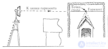
Single point perspective
In drawing A you can see: all seemingly parallel lines, extending from the front plane into the depth of the picture at certain angles, are found at one point of the vehicle. The bench on the right and the chest on the left in the near plan are below the horizon, so you can look at the bench seat or the inside of the chest; the closer to the vehicle would be these items, the worse their named elements would be available to your view.
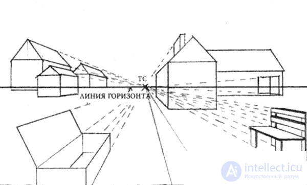
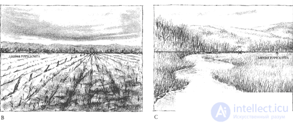
Figure B shows a plowed field. The furrows, like the rails, in the distance “stick” all into the same point of the vehicle, lying on the horizon line.
In Figure C, a meandering stream loses its apparent width, approaching the horizon line, and disappears altogether, crossing this line at a vehicle point.
Single Point Perspective
Perspective is a topic about which you can write a much bigger book than this. However, knowledge of even a few basic principles of perspective will help you to avoid many common mistakes and due to this, significantly improve the drawings.
The first most important principle is to always remember that the horizon line is at eye level. Even if there are mountains in the background of the picture, there is still a horizon line behind them, which can be indicated in the figure by a thin line. The second most important principle: all the horizontal lines that go deep into the picture are found at the vanishing point located on the horizon. Bearing in mind these two principles, carefully consider the three sketches in Figure 3.8 . These sketches show perspective with. single point of vanishing. So, on option A
railway rails and telegraph line converge at one point. It is easy to ensure that all telegraph poles look "correct" if, drawing the nearest pole, draw lines from its top and bottom to the vanishing point. In option B, light lines drawn from the corners of the nearest buildings in the foreground to the vanishing point will easily determine the correct location of all their doors and windows, as well as other buildings.
If you remember that the horizon is always at eye level, it will also be easy for you to determine the height of human figures and the approximate distance between them in your picture. If the soil is flat, the heads of people of average height will be just at the level of the horizon, the heads of stocky people below the horizon, and the basketball players above it
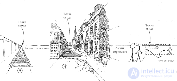
Figure 3.8.
In the perspective of a single vanishing point, the outgoing lines converge into a single point lying on the horizon. Figure A shows the telegraph line and railway rails, Figure B shows the street, Figure C shows the schematic figures of people. Notice that in Figure B, people's heads are on the horizon line, regardless of the distance at which the figures are drawn. The reason for this is that the horizon is always at eye level; exceptions to this rule are allowed only in cases when the object is viewed from above or below, as well as when people need to be drawn above or below average height. Figure B shows how you can easily determine the height of distant figures if they are at ground level.
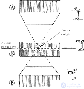
Figure 3.9.
Here it is shown how knowledge of the rules for constructing a perspective with a single vanishing point helps to create a design of objects that are (A) above, (B) at level and (C) below eye level. Draw such a box in perspective, and then “insert” into it the object you need - and you will not go wrong.
What the artist sees
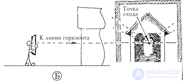
Figure 3.10.
Objects located below eye level will be below the horizon line (A) in the figure, of course, if you do not look down on them. And in option A, and B all the lines converge at one point on the horizon.
Light lines drawn from the legs and head of the nearest figure set the standard to determine the "correct" size of the removed figures. If the nearest figure and the figures in the background are not on the same line, then you should determine what the height of each of them should be, and then just move them to the right or left, as is done with the two most distant schematic silhouettes in Figure B.
If the object is located above eye level, then a part of its lower plane is visible (as in Figure 3.9 A); if below the eye level, its upper part (B) is visible; at eye level - neither one nor the other (B). Additionally, this is illustrated by Figure 3.10 A, where the schematically drawn artist looks at the covered bridge from the stairs, that is, from above. In his picture, the horizon is above the roof of the bridge. If the artist descends the stairs and looks at the bridge from the ground, he will see something similar to the image in Figure 3.10 B. In this case, the horizon will be closer to the center of the picture. Notice how in all cases all lines converge into one vanishing point. If at the stage of creating the composition of your drawing you spend a few minutes thinking through all these principles with a pencil in your hands, your work will become more convincing.
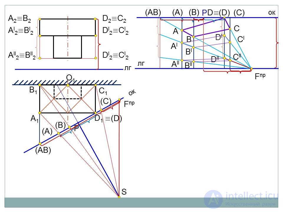
In architectural design, this method is most used. They are building the prospects for the main volumes of the structure, and the necessary detailing is carried out by various methods, one of which, by dividing the segment into equal and proportional parts, was introduced above. To build a perspective, it is necessary to draw the plan and the facade of the object. Further construction is carried out in three stages:
1. Selection point of view fig. 25, i.e. the choice of the position of the horizon line, the base of the picture and the point of standing in accordance with the recommendations given above.
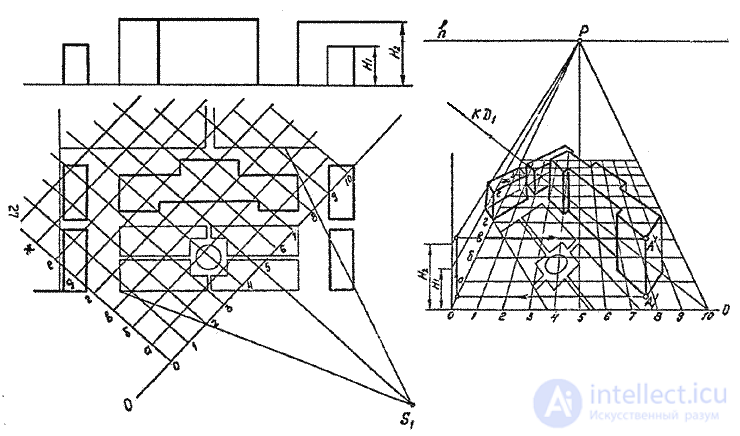
2. Building a building foundation perspective (plan perspective) fig. 26
As mentioned above, the perspective of the plan is constructed in the same way as the perspective of a planar quadrilateral (Fig. 13, 14).
With a normal height of the horizon (1.7 m) the distance from the base of the picture to the horizon line is small, so the plan in the future turns out to be compressed, “crumpled”, which makes it very difficult to build and further use. To get a more expanded plan, the subject plane can be lowered (or raised) to any distance, with the straight lines of this and the "omitted plan" going to the same vanishing points, while the plan points remain on the same verticals.
Building a "lowered plan" is recommended to more accurately fulfill the perspective of the object.
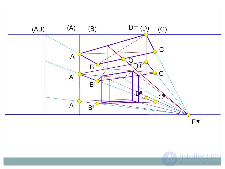
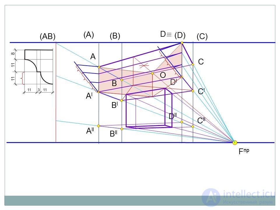
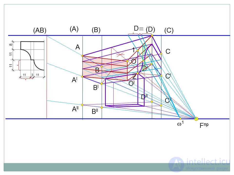
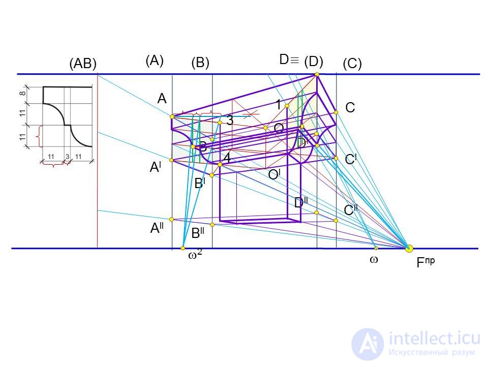
3. Building a building volume perspective.
To build spatial points of volume, you can use all the techniques explained above, or one of them.
If there are vertical edges or heights through which the picture passes, then it is convenient to begin building the perspective with them. From the grounds. these edges are restored perpendiculars and lay their true values on them. In turn, these verticals can serve as a “scale of heights” for other edges or vertical straight lines equal to them in height.
Other spatial points can be constructed as it is done in Fig. 16 or by building a “side wall”.
So, the construction of the perspective of the object by the method of architects is performed in the following sequence of fig. 27:
1. Draw the plan and the facade of a building or other object in a projection connection. In our drawing, besides the object itself, there is a vertical pole BA .
2. On the facade they draw the horizon line h , on the plan - the base of the picture O and determine the position of the standing point S 1 .
3. On the plan, the projections f and f 1 of the vanishing points of the two dominant directions of the plan are built, for which, from the standing point S 1, parallel to these directions, the rays are drawn to the intersection with the base of the picture. Build picture traces of all (visible and invisible) direct plan. In fig. 27 picture traces of "vertical" straight lines are designated by numbers 1, 2, 3; "horizontal" 1 o , 2 o , 3 o .
4. To simplify the construction, the picture plane is placed to the right of the facade in fig. 25 so that its base O coincides with the line of the base of the facade.
5. To build a "lowered plan," hold a "lowered base" O 1 , at an arbitrary distance from O and parallel to it.
6. On the object's plan, a strip of paper is applied to the base O and all points on the base are marked on it ( f 1 , 1, 2, 3 0 , P, 3 = 2 0 , 1 0 f 2 ).
7. A strip of paper is transferred and applied to the base of the picture O. All points from the strip of paper are transferred to the line O in the picture.
8. Through the points f 1 and f 2 draw vertical lines of communication to the intersection with the horizon line h, respectively, at the points F 1 and F 2 .
9. Picture traces from O line are transferred to O 1 also with the help of vertical communication lines.
 |
10. Build the perspective of the base of the object in the picture and the "plan omitted". Points 1, 2, 3, (from the bases O and O 1 ) are connected with F 2 , and 1 0 , 2 0 , 3 0 - with F 1 . The resulting figures should be outlined in brighter lines.
11. Build a volume perspective (spatial points or vertical edges). For convenience of explanation, we will call these vertical edges by their vertices. For example, edge "K" or edge "N" .
a) The edge "K" is located in the picture, therefore it is depicted in full size - from the point 3 = 2 o the perpendicular is restored and the height of this edge is transferred from the facade to it. The edge "K" serves as the "scale of heights" for the edge "L" , i.e. from "K" conduct a ray in F 1 , which cuts off point L ' on the corresponding perpendicular.
b) The perspective of the ribs "C" and "N" is determined by mentally transferring them to the picture in the direction F 1 1 0 . From the point 1 0 on the vertical straight line they lay the height H of these edges and connect the top point to F. This beam cuts off on the corresponding verticals C ' and N' .
c) To build the perspective of the pole BA, a "side wall" is built. A vertical line n is drawn in an arbitrary place, the height of the pole is laid on it from the base O , after which the lower and upper points are connected to an arbitrary point of the horizon line. Then from the base of the pole B 1 there is a broken line, in fig. 27 marked by arrows, which crossed the perpendicular from B ' at point A' .
d) All points constructed connect and lead the prospect with brighter lines. Denote points, lines and planes on perspectives is not accepted. Here it is made for convenience of explanations. Auxiliary rays and points are drawn and marked with thin lines and should not be removed.
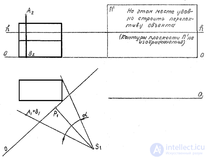 |
Fig.25
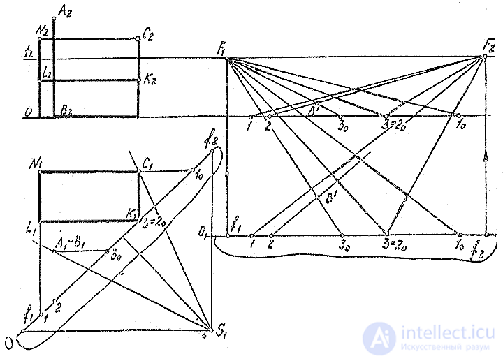 |
Fig.26
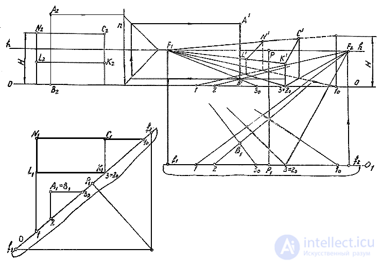 |
Fig.27
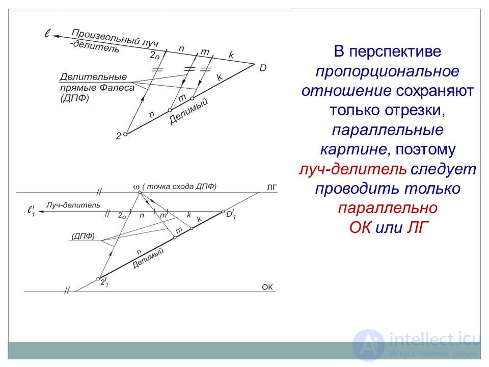
The division of segments (flat figures) into parts

Comments
To leave a comment
Descriptive Geometry and Engineering Graphics
Terms: Descriptive Geometry and Engineering Graphics