Lecture
The issues of ensuring the working drawing of the parts with the necessary dimensions are thought out already in the course of determining the necessary number and content of the images, and are directly solved only when the part images have already been completed.
Dimensions on the working drawing of the part must be applied in such a way as to ensure the least laboriousness of manufacturing the part. Failure to apply dimensions can lead to the implementation of unnecessary technological operations and an increase in the cost of the part. The presence of the same dimensions for individual elements of the part, for example, chamfers, grooves, grooves, reduces the number of necessary cutting and measuring tools, which leads to a decrease in the cost of manufacturing parts.
The general questions of dimensioning in drawings were considered in § 13. In this paragraph special issues are considered, taking into account the requirements of production in the manufacture of parts.
Dimensioning must comply with the technology of manufacturing the part, i.e. take into account the sequence of the work-processing of the workpiece and the equipment on which the part can be manufactured.
All dimensions of parts can be divided into two groups: mating and free (non-mating).
The mating dimensions determine the shape of the surface of the part mating with the surface of another part in the product, as well as the position of these surfaces in the product.
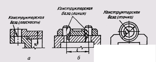
Fig. 264
The surfaces of the parts that are not in contact with the surfaces of other parts in the product are determined by the free dimensions.
All dimensions should be applied from the base surfaces, lines or points, relative to which the position of the individual elements of the part in the process of their manufacture or operation in the finished product is determined. Distinguish the base design, technological, measuring, assembly, auxiliary.
Design bases determine the position of the part in the finished product. In fig. 264 the plane (fig. 264, a), the line (fig. 264, b) and the point (fig. 264, c) are shown as design bases. In relation to the design base are oriented and other details of the product.
Technological bases determine the position of the part during processing.
The measuring (main) base is the base from which the dimensions are taken in the manufacture and control of the finished product (fig. 265). The hidden measurement base is the axis of rotation of the part.
Auxiliary bases help to count the sizes of the minor elements of the part. Auxiliary bases should be connected with the size of the main measuring base.
More dimensional surfaces should be chosen as dimensional bases. They must be processed first.
Parts dimensions can be applied from the bases in three ways: chain, coordinate and combined methods.
When dimensioning by chain, it is necessary to take into account that the dimensional chain is not closed. Each element or step of the part is processed independently (Fig. 266, a),
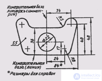
Fig. 265
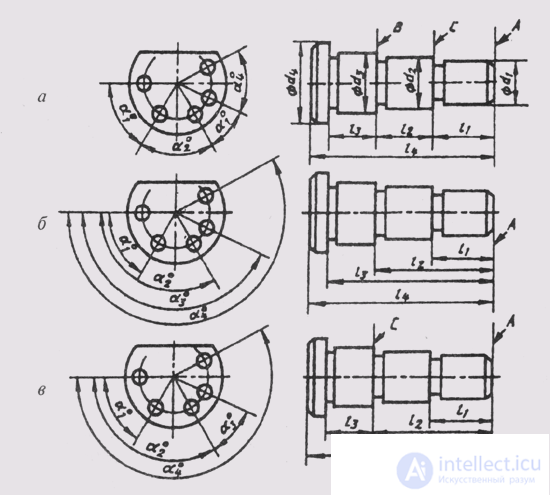
Fig. 266
i.e. first, a step of diameter d 1 is processed for a length l 1 from base A, then a step of diameter d 2 from base B , etc. The size of the section with diameter d 4 is determined by the overall dimension 4. If you need to specify the dimensions of all individual sections , the overall (total) size must be specified as a reference (size 84 in Fig. 265).
Dimensioning the chain leads to the summation of errors that appear in the process of manufacturing parts, which leads to more stringent requirements for controlling the total size.
The dimensions of the chain is applied in cases where it is necessary to accurately maintain the dimensions of the individual elements, and not the total size. The chain method is used for dimensioning the center distances when machining parts with a set of cutting tools, etc.
With the coordinate method, the dimensions are applied from the selected base (Fig. 266, b). Each size in this case is a coordinate, defining the position of the part element relative to the base. This method allows you to ensure high accuracy of execution of the size regardless of the performance of other sizes of parts.
The combined method of applying dimensions (Fig. 266, c) has found the widest application in practice, since it combines
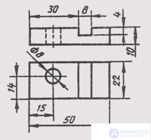
Fig. 267
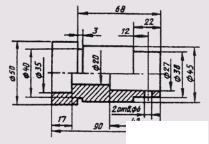
Fig. 268
features of both chain and coordinate methods. With this method, dimensions that require high precision performance can be separated from other sizes.
The dimensions between the surfaces to be machined and the surfaces that are not to be machined are separated into separate dimension chains, which must be interconnected by the same size.
When applying dimensions on the working drawings of parts, the following points must be observed.
1. A drawing of a part must contain three groups of dimensions necessary for its manufacture: overall, axial and center-to-center dimensions and their distances to the bases, the dimensions of the individual elements of the part.
2. In a number of cases, the installation, connection and reference dimensions are also affixed.
3. Each element of a part that is different from the other must have dimensions of its shape and dimensions relative to its bases. Each size is affixed to the same element only once. At the same time, for ease of use of the drawing, all the dimensions defining the part element should be concentrated in one main picture for the given element. In fig. 267 size and coordinates of the hole with a diameter of 8 mm are given in the top view, and the dimensions and coordinates of the groove - in the main view.
4. It is not allowed to mix the dimensions of the outer and inner surfaces of the elements of the part (Fig. 268). In this case, the dimension lines are preferably positioned outside the contour of the image. The intersection of the extension and dimension lines is undesirable, and it is strictly forbidden to tolerate a smaller size for a larger one. Dimensioning from the invisible contour line is not recommended.
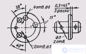
Fig. 269
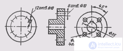
Fig. 270
5. The dimensions of several identical parts are applied once, with an indication of their number (fig. 269).
6. When applying dimensions of identical elements evenly spaced around the circle, instead of the angular dimensions coordinating the location of these elements around the circle, only their number can be indicated (Fig. 270).
7. Dimensions of symmetrically arranged elements are applied once without specifying their number (fig. 271), grouped in one place.
8. If identical elements are located on different surfaces of the part and are shown on different images, then the number of these elements is recorded separately for each surface (Fig. 272).
9. In fig. 273 shows examples of the application of the dimensions of the holes in the section and in the form, if there is no a section through the hole.
10. The same radii of rounding or bends can be recorded without indicating them on the images in the technical requirements of the type: “Radius of 5 mm”; "Unspecified radii of 3 mm"; "The inner radii of the folds of 12 mm."
11. For threaded parts, the length of the threaded section includes the size of the chamfer and groove. The dimensions of the chamfer and groove are specified separately within the size of the threaded section (Fig. 274).
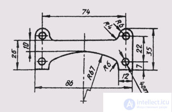
Fig. 271
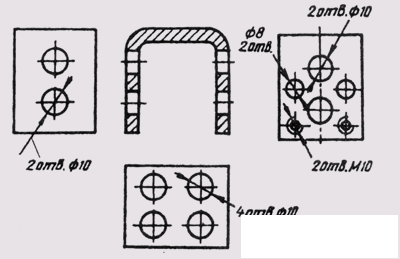
Fig. 272
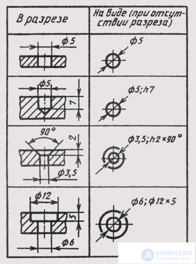
Fig. 273
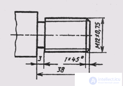
Fig. 274
12. When applying dimensions, it is necessary to take into account the requirements of standards for normal linear and angular dimensions, as well as GOST 2.307-68 and GOST 2.109-73.

Comments
To leave a comment
Descriptive Geometry and Engineering Graphics
Terms: Descriptive Geometry and Engineering Graphics