Lecture
Currently, mechanical engineering is widely used detachable connections: threaded, toothed (splined), key, pin, cotter pin, wedge, joint connection.
Large distribution in modern engineering received detachable connections of machine parts, carried out with the help of thread. A threaded joint can provide relative immobility of parts or movement of one part relative to another. The main connecting element in a threaded connection is a thread.
A thread is a surface formed by the screw movement of a flat contour along a cylindrical or conical surface. In this case, a screw protrusion of the corresponding profile is formed, bounded by helical and cylindrical or conical surfaces (Fig. 201, a).
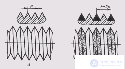
Fig. 201
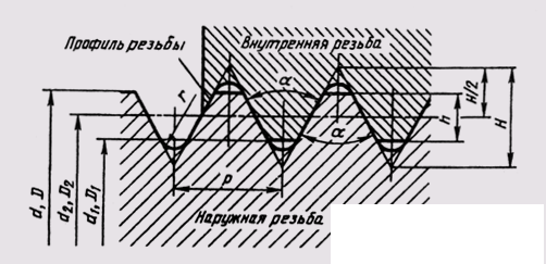
Fig. 202
Threads are classified according to the shape of the surface on which it is cut (cylindrical, tapered), according to the location of the thread on the surface of the rod or hole (external, internal), according to the shape of the profile (triangular, rectangular, trapezoidal, round), purpose (fixing, mounting and sealing). , running, special, etc.), the direction of the screw surface (left and right) and the number of entries (single and multiple).
All threads are divided into two groups: standard and non-standard; for standard threads, all their parameters are defined by standards.
The main parameters of the thread are defined by GOST 11708-82. The thread is characterized by three diameters: the outer d (D), the inner d 1 (D 1 ) and the middle d 2 (D 2 ).
The external thread diameters are d, d \, d 2 , and the internal threads in the hole are D, D 1 and D 2 .
The outer diameter of the thread d (D) is the diameter of an imaginary cylinder, described around the tops of the external or hollows of the internal thread. This diameter is decisive for most threads and is included in the thread symbol.
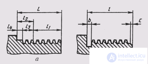
Fig. 203
The thread profile is the contour of the thread section by a plane passing through its axis (Fig. 201, 202).
The angle of the thread profile is the angle between the lateral sides of the profile (Fig. 202).
The thread pitch P is the distance between adjacent like sides of the profile in the direction parallel to the axis of the thread (Fig. 201).
The thread stroke t is the distance between the nearest like sides of the profile belonging to the same screw surface, in the direction parallel to the thread axis (Fig. 201). In a single thread (Fig. 201, a), the stroke is equal to the step, and in a multiple thread (Fig. 201, b) , the product of step P and the number of visits n (t = l P).
In fig. 203, and - the length of the thread l, the length of the thread with a full profile l 1 .
Thread runoff is a section of an incomplete profile in the thread transition zone to the main part of the object.
The underflow of the l 4 thread is the size of the non-cut part of the surface between the ends of the run and the bearing surface of the part.
Undercut / 2 includes runaway and underwater. To eliminate runaway or undercut, perform the groove b (Fig. 203, b).
To facilitate screwing the threaded rod, at the end of the thread perform a conical chamfer with an angle of 45 ° (Fig. 203, b).
Consider standard general purpose threads.
The thread metric is the main mounting thread. This thread is one-way, mostly right, with a large or small step. The profile of the metric thread is an equilateral triangle. The protrusions and gouges of the threads are blunted (fig. 204) (GOST 9150-81).
A cylindrical pipe thread has a profile in the form of an isosceles triangle with an apex angle of 55 ° (fig. 205), the tops and bottoms are rounded. This thread is used in pipelines and pipe connections (GOST 6351-81).
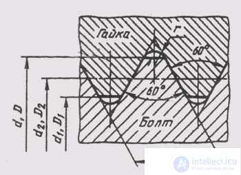
Fig. 204
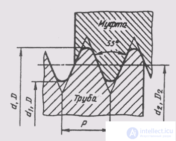
Fig. 205
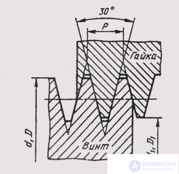
Fig. 206
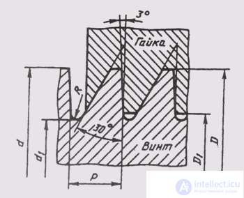
Fig. 207
Trapezoidal thread serves to transfer movement and effort. The trapezoidal thread profile is an equal-sided trapezoid with an angle between the lateral sides of 30 ° (fig. 206). For each diameter, the thread can be single-threaded and multiple, right and left (GOST 9484-81).
The resistant thread has an unequal trapezoid profile (fig. 207). Profile cavities are rounded, for each diameter there are three different steps. Serves for the transfer of motion with large axial loads (GOST. 10177-82).
The round thread for pedestals and holders, for safety glasses and lamps, for sanitary fittings (GOST 13536-68) has a profile obtained by conjugating two arcs of the same radius (fig. 208) (GOST 13536-68).
Conical inch thread with a profile angle of 60 ° (GOST 6111-52) is used for hermetic connections in pipelines of machines and machines; It is cut on a conical surface with a taper of 1:16; (Fig. 209).
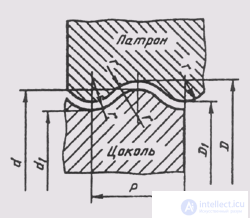
Fig. 208
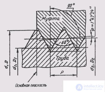
Fig. 209
Conical pipe thread has a profile similar to that of pipe pipe cylindrical; used in valves and gas cylinders. It is possible to connect pipes with a tapered thread (taper 1: 16) with products having a pipe cylindrical thread (GOST 6211-81).
Special threads are threads with a standard profile, but different from standard sizes of diameter or thread pitch, and threads with a non-standard profile.
Non-standard threads - square and rectangular (Fig. 210) - are made according to individual drawings, in which all parameters of the thread are set.
The image of the thread in the drawing is made according to GOST 2.311—68. On the rod, the threads are depicted as solid main lines in the outer diameter and in solid thin lines in the inner diameter. In fig. 211, and the carving on the cylinder is shown, and on fig. 211, b - on the cone.
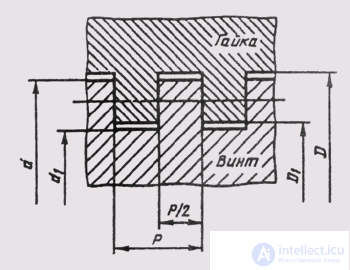
Fig. 210
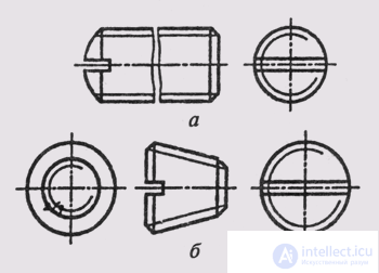
Fig. 211
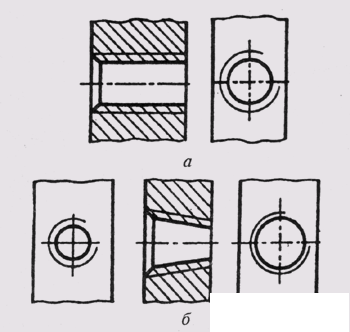
Fig. 212
In the hole, the threads are represented by solid main lines in the inner diameter and solid thin lines in the outer diameter. In fig. 212, and the thread is shown in a cylindrical bore, and in fig. 212, b - in conic.
On images obtained by projecting a threaded surface on a plane perpendicular to its axis, a continuous thin line is drawn with an arc 3/4 of the circumference, open at any place but not ending on the axes. When a thread is drawn, a solid thin line is drawn at a distance of at least 0.8 mm from the main line and not more than the size of the thread pitch. The visible thread boundary is drawn by a solid main line at the end of the full thread profile to the line of the outer diameter of the thread. The thread run is depicted as a solid thin line, as shown in fig. 213.
Chamfers on a threaded rod or in a threaded hole that do not have a special design purpose, are not depicted in the projection on a plane perpendicular to the axis of the rod or the hole. The solid thin line of the thread image should cross the line of the chamfer border (fig. 213, 214). Hatching in sections and sections is brought to a solid main line.
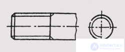
Fig. 213
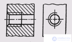
Fig. 214
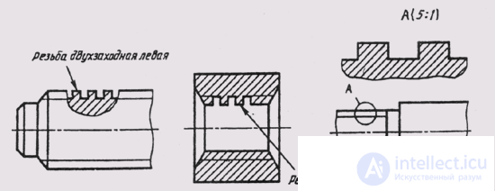
Fig. 215
A thread with a non-standard profile is depicted as shown in Fig. 215, with all sizes and additional data with the addition of the word “thread”.
In threaded connections, the thread is conventionally drawn on the rod, and in the hole, only that part of the thread that is not covered by the rod (Fig. 216).
Thread designation includes: thread type, size, thread pitch and stroke, tolerance range, accuracy class, thread direction, standard number.
The type of thread is conventionally denoted by:
M - metric thread (GOST 9150-81);
G - pipe cylindrical thread (GOST 6357-81);
T g - trapezoidal thread (GOST 9484-81);
S - resistant thread (GOST 10177-82);
Rd — round thread (GOST 13536-68);
R - pipe conical outer (GOST 6211-81);
Rr - internal conic (GOST 6211-81);
Rp - internal cylindrical (GOST 6211-81);
K - tapered inch thread (GOST 6111-52).
The size of the tapered threads and the pipe cylindrical thread is conventionally designated in inches (1 "= 25.4 mm), for all other threads the outer diameter of the thread is put in millimeters.
Thread pitch is not indicated for large pitch metric and for inch pitch
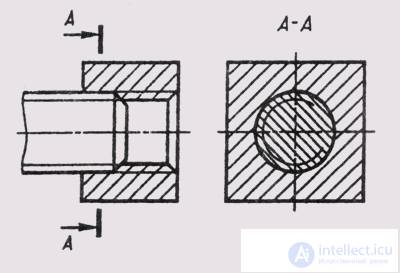
Fig. 216
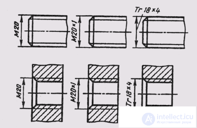
Fig. 217
threads, in other cases it is indicated. For multiple threads in the designation of the thread is included the thread, and the step is affixed in brackets.
The thread direction is indicated only for the left thread (LH).
The tolerance field and the accuracy class of the thread can be omitted from the training drawings.
Examples of thread designations:
M 30 - metric thread with an outer diameter of 30 mm and a large thread pitch;
M 30 x 1.5 - metric thread with an outer diameter of 30 mm, fine pitch 1.5 mm;
G 1 1/2-A - cylindrical pipe thread with a size of 1 1/2 ", accuracy class A;
T g 40x6 - single-thread trapezoidal thread with an outer diameter of 40 mm and a pitch of 6 mm;
T g 20 x 8 (P4) - two-way trapezoidal thread with an outer diameter of 20 mm, a stroke of 8 mm and a pitch of 4 mm;
S 80 x 10 - single-thread resistant thread with an outer diameter of 80 mm and a pitch of 10 mm;
S 80 x 20 (P10) - two-way resistant thread with an outer diameter of 80 mm, a stroke of 20 mm and a pitch of 10 mm;
Rdl6 - circular thread with an outer diameter of 16 mm;
Rdil6LH - round thread with a diameter of 16 mm, left;
R 1 1/2 - conical pipe thread with a size of 1 1/2 " .
K 1 1/2 GOST 6111-52 - inch tapered thread with a size of 1 1/2 ".
The designations of threads according to GOST 2.311-68 refer to the outer diameter, as shown in. Figure. 217.
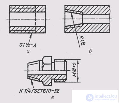
Fig. 218
The designation of tapered threads and tubular cylindrical threads is applied as shown in fig. 218, a, b, c.
The connection parts carried out with the help of threaded products.
Standard threaded products include fasteners (bolts, screws, nuts, studs). Technical requirements establish 12 accuracy classes for screws, bolts and studs and 7 accuracy classes for nuts. The types and symbol of coatings for fasteners are also established.
The structure of the symbols of fasteners includes:
7 - product name (bolt, screw, etc.);
2 - execution (execution I do not indicate);
3 - designation of a metric thread and its diameter;
4 - thread pitch (for small metric);
5 - designation of the thread tolerance range;
6 — length of bolt, screw, stud in mm; 7 — accuracy class;
8 - steel or alloy;
9 - designation of the type of coverage;
10 - coating thickness in mm;
11 - the number of the standard for the design of the fastener and its dimensions.
On training drawings, positions 5, 7, 8, 9, 10 in the course of engineering graphics may not include in the condition the designation of the product, since these parameters can reasonably be assigned without special knowledge.
The bolt is a cylindrical rod with a head at one end and a thread at the other end. Bolts are used (together with nuts, washers) to fasten two or more parts. There are various types of bolts, differing from each other in shape and size of the head and rod, in the pitch of the thread, in the accuracy of manufacture and in execution.
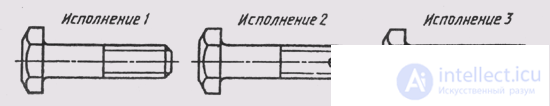
Fig. 219
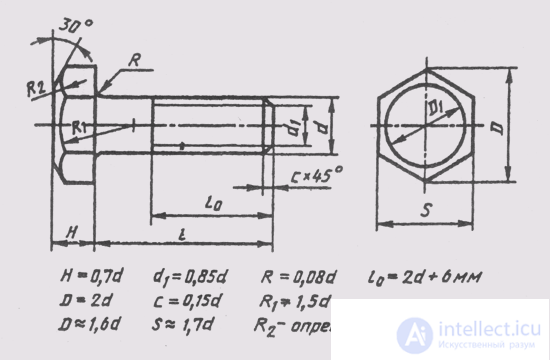
Fig. 220
Hexagonal bolts have from three (fig. 219) to five versions: version 1 - without holes (in the head and rod); version 2 - with a hole in the threaded part of the rod; execution 3 - with two holes in the bolt head.
When depicting a bolt in the drawing, two types are performed (Fig. 220) according to the general rules and they are applied to dimensions of the length l of the bolt, the length of the thread / o, the size of the key S and the designation of the thread Md. H height of the head in the length of the bolt does not turn on. Hyperbolas, formed by the intersection of the conical chamfer of the bolt head with its faces, are replaced by other circles.
Examples of bolt symbols:
Bolt Ml2 x 60 GOST 7798-70 - with a hexagonal head, first performance, with M12 thread, large thread pitch, bolt length 60 mm.
Bolt 2M12 x 1.25 x 60 GOST 7798-70 - with a small metric thread M12x1.25, the second version, the bolt length 60 mm.
The screw is a cylindrical rod, at one end of which a thread is made, at the other end there is a head. By purpose, the screws are divided into mounting and installation. Screw fasteners are used to connect parts by screwing a screw with a threaded part into one of the parts to be joined.
Set screws are used for fixing parts together. Their core is cut completely; they have a pressure end of a cylindrical or conical shape or a flat end (fig. 221).
The fastening screws come in four versions; Execution 1 - thread diameter larger than the diameter of the smooth part of the rod (Fig. 222); execution 2 - thread diameter equal to the diameter of the smooth part; version 3 and the screw head has a cross-shaped slot for a screwdriver.
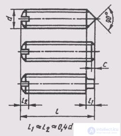
Fig. 221
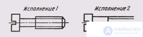
Fig. 222
Depending on the working conditions, screws are made (fig. 223) with a cylindrical head (GOST 1491-80), a semicircular head (GOST 17473-80), a semi-secret head (GOST 17474-80) or a countersunk head (GOST 17475-80) with a slot , and also with a turnkey head and with a corrugation.
The height of the head in the length of the screw is not included, with the exception of countersunk head screws (Fig. 223).
In the drawing, the form of a slotted screw completely conveys one image on a plane, parallel to the axis of the screw. At the same time indicate the size of the thread, the length of the screw, the length of the cut part (lо = 2 d + 6 mm) and the symbol of the screw according to the corresponding standard.
Examples of symbols for screws:
Screw M12x50 GOST 1491-80 — with a cylindrical head, of the first performance, with M12 thread with a large pitch, 50 mm long;
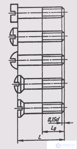
Fig. 223
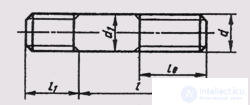
Fig. 224
Screw 2M12x1, 25x50 GOST 17475-80 — with countersunk head, second performance, with a small metric thread with a diameter of 12 mm and a pitch of 1.25 mm, a screw length of 50 mm.
The hairpin is a cylindrical rod with a thread at both ends (Fig. 224). The stud serves to connect two or more parts. One end of the stud 1 \ is screwed into the threaded hole of the part, and the nut is screwed onto the other end / o. The studs are produced with two threaded ends of the same length for parts with smooth through holes. The length of the smooth part of the stud stud must be at least 0.5 d.
The design and dimensions of the studs are determined by the standards depending on the length of the threaded end:
GOST 22032-76l 1 = 1.0d - the pin is screwed into steel, bronze, brass;
GOST 22034–76 l 1 , = 1,25d; GOST 22036-76l 1 = 1,6d - a pin is screwed into cast iron;
GOST 22038–76 l 1 = 2 d ; GOST 22040–76 l 1 = 2.5d — a pin is screwed into light alloys.
When depicting a stud, they draw only one view on a plane parallel to the axis of the stud, and indicate the dimensions of the thread, the length / stud and its symbol. Examples of pin symbols:
Hairpin M8 x 60 GOST 22038-76 - with a large metric thread with a diameter of 8 mm, hairpin length 60 mm, designed for screwing into light alloys, the length of the screwed-in end 16 mm;
The M8 x 1.0 x 60 GOST 22038-76 hairpin is the same, but with a fine thread pitch —1.0 mm.
The nut is a fastener with a threaded hole in the center. It is used for screwing onto a bolt or a pin all the way into one of the parts to be joined. Depending on the name and working conditions, the nuts are made with hex, round, wing, shaped, etc. Hexagon nuts have the greatest use. They are made in three versions: execution l - with two conical chamfers (Fig. 225); execution 2 - with one conic chamfer; execution 3 - without chamfers, but with a conical protrusion from one end.
The nut form on the drawing completely conveys its two types: on the plane of the projections parallel to the axis of the nut, half of the type is combined with half of the frontal section, and on the plane perpendicular to
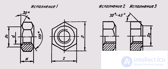
Fig. 225
nut axis, on the chamfer side. In the drawing indicate the size of the thread, the size of S turnkey and give the designation of the nut according to the standard.
Examples of a symbol of nuts:
Nut M12 GOST 5915-70 - first performance, with a thread diameter of 12 mm, a large thread pitch;
Nut 2M12 x 1.25 GOST 5915-70 - second performance, with a small metric thread with a diameter of 12 mm and a pitch of 1.25 mm.
The washer is a chiseled or stamped ring, which is placed under the nut, screw or bolt head in threaded connections. The washer plane increases the bearing surface and protects the part from scoring when the nut is screwed on with a key. In order to protect the threaded joint from spontaneous unscrewing under conditions of vibration and alternating load, spring washers are used according to GOST 6402-70 and stop washers having lugs-tabs.
Round washers according to GOST 11371-78 have two versions (fig. 226): version 1 - without chamfer, version 2 - with a chamfer. The shape of a round washer completely conveys one image on a plane parallel to the axis of the washer.
The inner diameter of the washer is usually 0.5 ... 2.0 mm larger than the diameter of the bolt rod on which the washer is worn. The diameter of the thread of the rod is included in the symbol of the washer, although the washer itself does not have a thread.
Examples of the symbol of the puck:
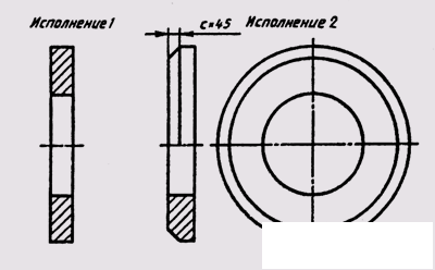
Fig. 226
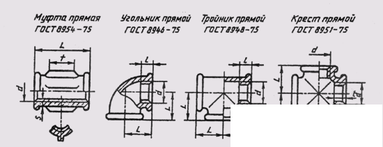
Fig. 227
Washer 20 GOST 11371—78 - round, first performance, for bolt with M20 thread;
Washer 2.20 GOST 11371—78 - the same washer, but the second performance.
Соединительные детали трубопроводов (муфты, угольники, тройники и т. д.) представляют собой резьбовые соединения, изготовленные из ковкого чугуна и предназначенные для соединения труб в трубопроводах (рис. 227). Трубы используются в коммуникациях, транспортирующих жидкость или газ, а также для прокладки кабеля.
Конструкция и размеры соединительных деталей трубопроводов определены стандартами. Концы труб имеют резьбу наружную, а соединительные детали — внутреннюю. Основным параметром деталей трубных соединений является условный проход Dy — внутренний диаметр труб в миллиметрах. Соединительные детали трубопроводов имеют покрытие в основном цинковое.
Примеры условных обозначений соединительных деталей трубопроводов:
Муфта длинная 20 ГОСТ 8955—75 — прямая, неоцинкованная, для труб с условным проходом 20 мм;
Угольник Ц-25 ГОСТ 8946—75 — прямой, оцинкованный, для труб с условным проходом 25 мм.
Изображения резьбовых соединений на чертежах выполняются в соответствии с требованиями стандартов.
Резьбовые соединения являются неподвижными резьбовыми соединениями. К ним относят соединения деталей с помощью болтов, винтов, шпилек, гаек и соединительных деталей трубопроводов.
Изображение резьбового соединения состоит из изображенных и соединяемых деталей.
Различают конструктивное, упрощенное и условное изображения крепежных деталей и их соединений. При конструктивном изображении
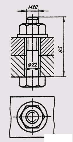
Fig. 228
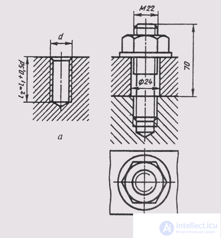
Fig. 229
размеры деталей и их элементов точно соответствуют стандартам. При упрощенном изображении размеры крепежных деталей определяют по условным соотношениям в зависимости от диаметра резьбы и упрощенно вычерчивают фаски, шлицы, резьбу в глухих отверстиях и т.д.
Условные обозначения используются при диаметрах стержней крепежных деталей 2 мм и менее. Изображения упрощенные и условные крепежных деталей установлены ГОСТ 2.315—68. В настоящем разделе приводятся упрощенные изображения крепежных деталей в резьбовых соединениях, рекомендуемые в учебных чертежах.
The bolted joint consists of a bolt, nut, washer and the parts to be joined. Through holes with a diameter of d 0 = (1.05 ... 1.10) d are drilled in the parts to be joined , where d is the diameter of the bolt thread. A bolt is inserted into the hole, a washer is put on it and the nut is screwed all the way (fig. 228).
The length of the bolt is determined by the formula l = H 1 + H 2 + S W + H + K, where H 1 and H 2 are the thickness of the parts to be joined; S m - thickness of the washer, S W = 0.15 d; H — nut height, H = 0.8 d; K - the length of the protruding rod bolt, K = 0.35d.
Расчетную длину болта округляют до ближайшей стандартной длины болта.
На чертеже болтового соединения (рис. 228) выполняют не менее двух изображений — на плоскости проекций, параллельной оси болта, и на плоскости проекций, перпендикулярной его оси (со стороны гайки). При изображении болтового соединения в разрезе болт, гайку и шайбу показывают неразрезанными. Головку болта и гайку на главном виде изображают тремя гранями. Смежные детали штрихуют с наклоном в разные стороны. На чертеже болтового соединения указывают три размера: диаметр резьбы, длину болта и диаметр отверстия под болт.
Условные обозначения болта, гайки и шайбы записываются в спецификации сборочного чертежа (см. § 101).
Шпилечное соединение состоит из шпильки, шайбы, гайки и соединяемых деталей. Соединение деталей шпилькой применяется тогда, когда нет места для головки болта или когда одна из соединяемых деталей имеет значительную толщину. В этом случае экономически нецелесообразно сверлить глубокое отверстие и ставить болт большой длины. Соединение шпилькой уменьшает массу конструкций. Одна из соединяемых шпилькой деталей имеет углубление с резьбой — гнездо под шпильку, которая ввинчивается в него концом l 1 (см. рис. 224). Остальные соединяемые детали имеют сквозные отверстия диаметром d 0 = (1,05...1,10)d, где d —диаметр резьбы шпильки. Гнездо сначала высверливается на глубину l 2 , которая на 0,5d больше ввинчиваемого конца шпильки, а затем в гнезде нарезается резьба. На входе в гнездо выполняется фаска с = 0,15d (рис. 229, а). При ввинченной в гнездо шпильке соединение деталей дальше осуществляется как в случае болтового соединения.
Длину шпильки определяют по формуле l = H 2 + S Ш + Н+ К, где H 2 — толщина присоединяемой детали; S Ш — толщина шайбы; Н — высота гайки; К —длина выступающего конца над гайкой. Расчетную длину шпильки округляют до стандартного значения.
На чертеже шпилечного соединения линия раздела соединяемых деталей должна совпадать с границей резьбы ввинчиваемого резьбового конца шпильки (рис. 229, б). Гнездо под шпильку оканчивается конической поверхностью с углом 120°. Нарезать резьбу до конца гнезда практически невозможно, но на сборочных чертежах допускается изображать резьбу на всю глубину гнезда. На чертеже шпилечного соединения указывают те же размеры, что и на чертеже болтового соединения. Штриховку в резьбовом соединении шпильки с деталью, в которую шпилька ввинчена, в разрезе доводят до сплошной основной линии резьбы на шпильке и в гнезде.
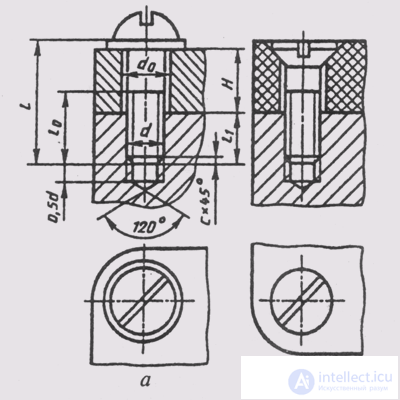
Fig. 230
Соединение винтом включает соединяемые детали и винт с шайбой. В соединениях винтами с потайной головкой и установочными винтами шайбу не ставят.
У одной из соединяемых деталей должно быть гнездо с резьбой для конца винта, а в другой - гладкое сквозное отверстие диаметром dо = =(1,05...1,10)d. Если применяется винт с потайной или полупотайной головкой, то соответствующая сторона отверстия детали должна быть раз-зенкована под головку винта (рис. 230).
Длина винта определяется по формуле l = Н = S Ш + l 1 , где Н — толщина присоединяемой детали; S Ш — толщина шайбы; l 1 — длина ввинченного резьбового конца винта, которая назначается для соответствующего материала, как для шпильки.
Расчетная длина винта округляется до стандартного значения длины.
Изображение винтового соединения на чертеже выполняется подобно болтовому соединению по относительным размерам. Относительные размеры головок винта указаны на рис. 231.
На винтовом соединении граница резьбы на стержне винта должна находиться внутри гладкого отверстия, запас резьбы, не использованный при ввинчивании, равен примерно трем шагам резьбы (З.Р). Если диаметр головки винта меньше 12 мм, то шлиц рекомендуется изображать одной утолщенной линией. На виде сверху шлиц в головке показывается повернутым на 45°. На чертеже соединения наносят три размера: диаметр резьбы, длину винта, диаметр отверстия для прохода винта.
Трубное соединение состоит из соединяемых труб и соединительных деталей трубопроводов. При соединении двух труб муфтой кроме муфты в соединение входят контргайка и прокладка (рис. 232).
Чертежи трубных соединений выполняются по размерам их деталей как конструктивные чертежи, без упрощений. Перед тем как приступить к вычерчиванию трубного соединения, необходимо по значе-
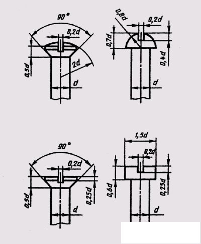
Fig. 231
нию условного прохода D y подобрать по таблицам соответствующих стандартов размеры труб и соединительных частей.
Более подробно правила выполнения чертежей труб и трубопроводов изложены в ГОСТ 2.411—72.
Винтовые (ходовые) соединения относятся к подвижным разъемным соединениям. В этих соединениях одна деталь перемещается относительно другой детали по резьбе. Обычно в этих соединениях применяются резьбы трапецеидальная, упорная, прямоугольная и квадратная. Чертежи винтовых соединений выполняются по общим правилам.
Зубчатое (шлицевое) соединение представляет собой многошпоночное соединение, в котором шпонка выполнена заодно с валом и расположена параллельно его оси. Зубчатые соединения, как и шпоночные, используются для передачи крутящего момента, а также в конст-
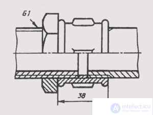
Fig. 232
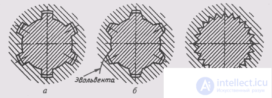
Fig. 233
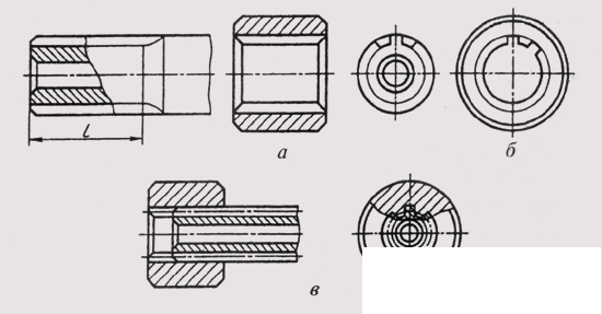
Fig. 234
рукциях, требующих перемещения деталей вдоль оси вала, например в коробках скоростей.
Благодаря большому числу выступов на валу зубчатое соединение может передавать большие мощности по сравнению со шпоночным соединением и обеспечивать лучшую центровку вала и колеса.
По форме поперечного сечения зубья (шлицы) бывают прямобочные, эвольвентные и треугольные (рис. 233).
ГОСТ 2.409—74 устанавливает условные изображения зубчатых валов, отверстий и их соединений.
Окружности и образующие поверхности выступов (зубьев) валов и отверстий показывают на всем протяжении основными линиями (рис. 234). Окружности и образующие поверхностей впадин показывают сплошными тонкими линиями, а на продольных разрезах — сплошными основными линиями.
При изображении зубчатых соединений и их деталей, имеющих эвольветный или треугольный профиль, делительные окружности и
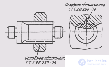
Fig. 235
образующие делительных поверхностей показывают штрих-пунктирной тонкой линией (рис. 234, б).
На плоскости, перпендикулярной оси зубчатого вала или отверстия, показывают профиль одного зуба (выступа) и двух впадин, а фаски на конце шлицевого вала и в отверстии не показывают.
Границу зубчатой поверхности вала, а также границу между зубьями полного профиля и сбегом показывают сплошной тонкой линией (рис. 234, а).
На продольных разрезах зубья условно совмещают с плоскостью чертежа и показывают нерассеченными, а в соединениях в отверстии показывают только ту часть выступов, которая не закрыта валом (рис. 234, б).
Условное обозначение шлицевого вала или отверстия по соответствующему стандарту помещается в таблице параметров для изготовления и контроля элементов соединения. Условное обозначение соединения допускается указывать на чертеже с обязательной ссылкой на стандарт на полке-выноске, проведенной от наружного диаметра вала (рис. 235).
Соединение шпоночное состоит из вала, колеса и шпонки. Шпонка (рис. 236) представляет собой деталь призматической (шпонки призматические или клиновые) или сегментной (шпонки сегментные) формы, размеры которой определены стандартом. Шпонки применяют для передачи крутящего момента.
В специальную канавку-паз на валу закладывается шпонка. На вал насаживают колесо так, чтобы паз ступицы колеса попал на выступающую часть шпонки. Размеры пазов на валу и в ступице колеса должны соответствовать поперечному сечению шпонки.
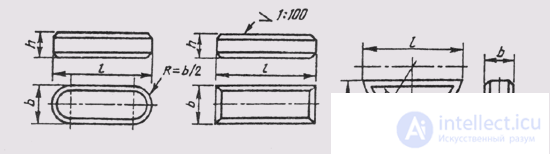
Fig. 236
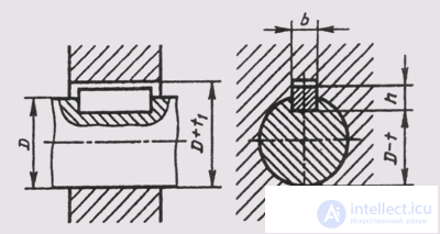
Fig. 237
Размеры призматических шпонок определяются ГОСТ 23360—78; размеры соединений с клиновыми шпонками — ГОСТ 24068—80; размеры соединений с сегментными шпонками — ГОСТ 24071—80.
Шпонки призматические бывают обыкновенные и направляющие. Направляющие шпонки крепят к валу винтами; их применяют, когда колесо перемещается вдоль вала.
По форме торцов шпонки бывают трех исполнений: исполнение
1 — оба торца закруглены; исполнение
2 — один торец закруглен, второй — плоский; исполнение
3 — оба торца плоские.
Рабочими поверхностями у шпонок призматических и сегментных являются боковые грани, а у клиновых верхняя и нижняя широкие грани, одна из которых имеет уклон 1 : 100.
Поперечные сечения всех шпонок имеют форму прямоугольников с небольшими фасками или скругленными. Размеры сечений шпонок выбираются в зависимости от диаметра вала, а длина шпонок — в зависимости от передаваемых усилий.
Условные обозначения шпонок определяются стандартами и включают в себя: наименование, исполнение, размеры, номер стандарта. Пример условного обозначения шпонки:
Шпонка 10 х 8 х 60 ГОСТ 23360—78 — призматическая, первого исполнения, с размерами поперечного сечения 10x8 мм, длина 60 мм.
Drawings keyed connections are carried out by the general rules. Keyway connection is shown in the frontal section of the axial plane (Fig. 237). The key is depicted uncut, a local incision is made on the shaft. The second image of the keyed connection is a section of a plane perpendicular to the axis of the shaft. The gap between the bases of the groove in the sleeve (wheel hub) and the key is shown increased.
The pin connection (fig. 238) - cylindrical or conical - is used for precise mutual fixation of the fastened parts. Cylindrical pins ensure repeated assembly and disassembly of parts.
Splinters are used to limit the axial movement of parts (fig. 239) of locking crown nuts.
The wedge connections (fig. 240) ensure easy disassembly of the parts to be joined. Faces of wedges have a slope of 1/5 to 1/40
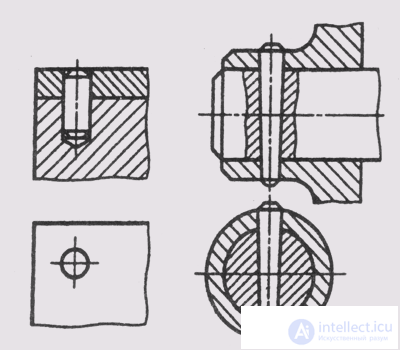
Fig. 238
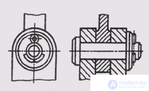
Fig. 239
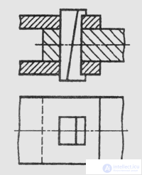
Fig. 240
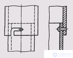
Fig. 241
In joints with an articulation (fig. 241), the protrusion of one part fits into the groove or hole of another part; parts are rotated relative to each other, and thus ensured their connection.

Comments
To leave a comment
Descriptive Geometry and Engineering Graphics
Terms: Descriptive Geometry and Engineering Graphics