Lecture
As already noted, when converting a complex drawing, it is possible to change the position of the specified geometric elements relative to the planes of projections with a constant position of the main planes of projections. This is done by rotating these elements around a certain axis until these elements occupy a particular position in the original system of planes. This transformation of the complex drawing is called the rotation method.
In this case, as the axis of rotation, it is most convenient to choose projecting straight or straight levels, then the point will rotate in planes parallel or perpendicular to the planes of the projections.

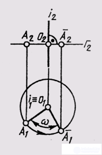
Fig. 115

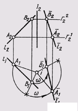
Fig. 116
When rotating around a horizontally projecting straight line, the horizontal projection A 1 of point A moves in a circle, and frontal AI in a straight line, perpendicular to the frontal projection of the axis, which is the front projection of the plane of rotation G 2 (Fig. 115). At the same time, the distance between the horizontal projections of two points A and B (fig. 116) when they are turned by the same angle с remains unchanged (А 1 В 1 = А 1 B 1 ).
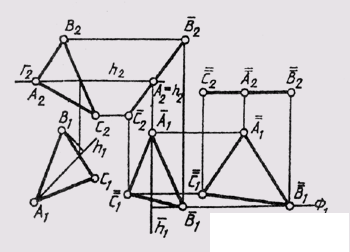
Similar conclusions can be made for rotation around a frontal projecting straight line. When a flat figure rotates around an axis perpendicular to the plane of projections, its projection on this plane does not change in size or shape, since the inclination of the flat figure to this plane does not change, but only the position of this projection relative to the communication line. The second projection on a plane parallel to the axis of rotation varies both in shape and in magnitude. The projections of points on this projection plane are on straight lines perpendicular to the original communication lines. Using these properties, you can use the method of rotation for converting a drawing without setting the image to the axis of rotation and not setting the value of the rotation radius. This is a method of plane-parallel movement, in which all points of a geometric figure move in mutually parallel planes without changing the actual appearance and size of this figure (Fig. 117).
The triangle ABC occupies a common position. With the first plane-parallel movement, he is placed in a frontally projecting position with the help of the horizontal line h, which we locate as a frontally projecting straight line in its plane of rotation G || P. At that, А 1 В 1 С 1 = А 1 В 1 С 1 , and the planes of rotation of points B and C are parallel to the plane G.
The second movement of the ABC is parallel to the plane P 1 . The degenerate frontal projection of the triangle ( А 2 В 2 C 2 = А 2 В 2 С 2 ) was left without change , and the new horizontal projection, which gives the true value ABC, was obtained by constructing new horizontal projections that

Fig. 117

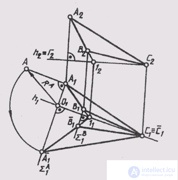
Fig. 118
A 1 B 1 check and С 1 as a result of their rotation in parallel frontal planes of the level ( B 2 ~ F; B ~ F).
This example is used to construct the solution of the third and fourth initial problems by transforming a complex drawing of a plane of general position using the method of plane-parallel displacement.
If we take the level line as the axis of rotation, then the true value of the flat figure of general position can be built with one turn, that is, you can avoid double transformation of the drawing, which took place in replacing the projection planes and plane-parallel movement. In fig. 118 an ABC image (A 1 B 1 C 1 ) is constructed after turning it around the horizontal line h (C, 1) of level T ~ h. Since the horizontal passes through point C, the latter is stationary as the triangle rotates. It is necessary to rotate only points A and B around the horizontal to coincide with the plane G || P 1 . Point A rotates in the horizontally projecting plane Sum A , perpendicular to the axis of rotation. The center of rotation About point A lies on the axis of rotation. At the moment when, as a result of the rotation, point A will be in the plane D, i.e. it will align with the horizontal plane of the level, its horizontal projection A 1 will be removed from the horizontal projection of the axis of rotation h 1 by a distance equal to the true value of the radius of rotation R A of point A The natural size R A can be constructed as the hypotenuse O \ A of a right triangle (see § 42), one leg of which is the horizontal projection of radius A 1 O 1 , and the second is the difference of the heights of points A and O. Having built the combined horizontal projection of point A, easy complete the image of the entire triangle А 1 B 1 C 1 in the position aligned with the plane G, using a fixed point and the plane of rotation of point B (Sum B 1 _ | _ h 1 ). The frontal projection of ABC will degenerate into a straight line and align with the projection G 2 of the alignment plane.
Similar actions are performed when rotating a flat figure around its front. The combination in this case is carried out with the front
the plane of the level (Ф || П 2 ) passing through the axis of rotation - the frontal.
Other problems can be solved using the rotation method as applied to their conditions.
Comments
To leave a comment
Descriptive Geometry and Engineering Graphics
Terms: Descriptive Geometry and Engineering Graphics