Lecture
Applied
when building a perspective of objects with irregular shapes;
different directions of straight lines; large distances to vanishing points; high horizon
This way they build perspectives with a high horizon of master plans for building up plots; structures having a complex configuration in the plan; flat ornaments.
The essence of the method consists in drawing a grid on the plan, taking the side of the square (cell) per unit length; build the grid perspective, draw the outline of the plan in the appropriate, perspective squares and then use the "scale of heights" to determine the perspectives of spatial points (vertical edges).
Let us consider an example of building a perspective of a building site using the grid method (Fig. 28)
 |
1. Draw a plan and facade of the site.
2. Choose a point of view in accordance with the recommendations given above, i.e. on the plan spend the base of the picture and choose the position of the standing point. On the facade they draw the horizon line at a level that is two to three times the height of the tallest building.
3. A grid of straight lines is applied to the plot plan so that the direction of some straight lines is parallel to the base of the picture, while others are perpendicular. The squares on the plan, and then in the future the same designate. For example, as shown in fig. 28, on one side - in letters, on the other - in numbers.
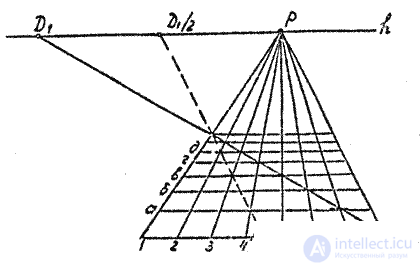
4. Build a grid perspective, given that the vanishing point of lines that are perpendicular to the picture is the main point of the picture. The other sides remain parallel to the base of the picture, and their position is determined using distance points (Fig. 29). If distance points are outside the sheet, use fractional distance points. For example, D / 2 , as shown in fig. 29. In this case, you can determine the position of every second of the "horizontal lines" of the grid. To find the intermediate lines, you can draw another straight line - to the D / 2 point through the middle of any "horizontal" side of the square.
5. Introduce the plot plan into the grid perspective cells by interpolating "by eye".
6. Perspectives of spatial points (heights) can be constructed using “side walls”. It is also convenient to use a vertical plane perpendicular to the picture instead of the “side wall”. Horizontals in perspective will go to the main point of the picture. On a vertical straight line, the intersection of this plane with the picture is set aside from the base of the height of the structures, using grid cells as a scale scale. From the marked points hold the perspectives of the contours in the main point of the picture. Then, from the perspectives of the bases, the vertical edges are broken to the intersection with the perspective of the heights at their upper points. In fig. 28 shows the construction of the perspective of point A.
Comments
To leave a comment
Descriptive Geometry and Engineering Graphics
Terms: Descriptive Geometry and Engineering Graphics