Lecture
All parts can be divided into three groups: standard parts, parts with standard images, original parts.
The standard parts include previously considered fasteners (bolts, screws, nuts, studs), washers, pins, cotter pins, keys, pipe fittings. Standards regulate not only the shape and dimensions of these parts, but also their images and the application of dimensions and signs of roughness.
The group of standards ESKD (GOST 2.401-68 ... GOST 2.426-74) regulates only standard images of parts and specifies the rules for applying dimensions to the images of these parts. Such details include springs, gears, slats, worms, sprockets, etc.
Original parts include such parts, the shape of which differs from the shape of the parts of the first two groups. These include cast parts, parts manufactured by punching or forging, parts that have the form of surfaces of revolution, parts that are limited mainly by planes, etc. The shape of these parts is determined by the technology of their manufacture and carries elements characteristic of this technology. Cast parts have casting slopes and rounding, turning parts have turning surfaces prevailing, etc.
Cast parts are widely used. These are individual machine parts, such as flywheels, pulleys, cylinders, caps, levers, these are parts such as supports, brackets, these are box-shaped case parts of a closed or open type, with precisely machined holes and flat outer surfaces.
The total number of images in the casting drawing depends largely on the correct selection of the main view, on the reasonable use
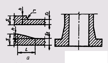
Fig. 280
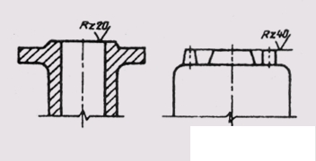
Fig. 281
use of permissible GOST 2.305 - 68 combinations of species with cuts, local cuts, sections of external elements, conventions and simplifications.
The box-type body parts are positioned relative to the frontal plane of the projections so that their main base surfaces are horizontal and the parts such as flanges or pulleys are projected parallel to the main inscription of the drawing, since this arrangement corresponds to the position of the part during its turning.
When making drawings of cast parts, the following requirements should be considered.
one . Foundry biases in the drawing do not depict, limited to the corresponding entry in the technical requirements.
2. In order for a part to have no internal stresses and casting defects, it is necessary to make a smooth transition from one wall thickness to another according to the standards given in fig. 280, and:
S / S 1 = <2; r = (0.3 ... 0.4) h;
S / S 1 > 2; l = (4 ... 5) h;
3. The support shoulders (flanges) must be thicker than the main part of the part. In this case, it is necessary to provide a smooth transition from the wall to the flange (Fig. 280, b).
4. The surfaces to be treated need to be raised above the non-machined ones. This will provide a free exit to the cutting tool and reduce the machining area (fig. 281).
5. If the base plate is mounted on another part, then the attachment plane is made non-continuous in order to reduce the treatment area (Fig. 282, a). With the same purpose, the middle part of the
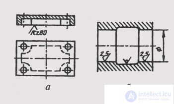
Fig. 282
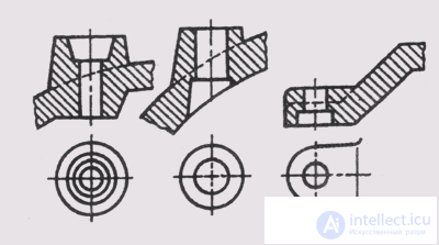
Fig. 283
Steps perform a larger diameter than the end working parts of the hole, where the shaft mates with the hole (Fig. 282, b).
6. The surfaces in which the holes are drilled are made with tides, the end planes of which should be perpendicular to the axis of the hole (Fig. 283).
When applying cuts in the drawings of cast parts, the following features should be considered: a) the relative position of the non-machined surfaces of the parts indicate the dimensions that bind these surfaces together; b) machined surfaces and non-machinables are interconnected by no more than one dimension in length, height or depth of the part.
Before applying the dimensions, it is necessary to choose the main foundry and design bases. Foundry bases can be axes or planes of symmetry or unworked surfaces. From the foundry bases put the dimensions that determine the shape and position of uncultivated surfaces. Separately, they apply dimensions that determine the shape and position of the surfaces to be treated relative to the design bases.
Dimensions in casting drawings are not allowed to be applied in the form of a closed circuit. On the working drawing of the molded part must be placed technical requirements. In the technical drawings, the technical requirements can only be limited to indicating the sizes of unspecified casting radii and sizes for reference.
In fig. 284 images are shown and the sizes of the cover received by machining from casting are put. The end face of the part and the axis of the surface of the protrusion, diameter 70, were taken as the foundry bases, and the reference end and the axis of the surface 0 72, which coincides with the foundry base, were used as the design bases. At the same time, the overall size 38 is at the same time the size between the foundry and design bases in the longitudinal direction.
Parts having the form of rotation bodies are machined mainly on lathes and similar machines. These details are important
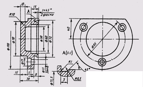
Fig. 284
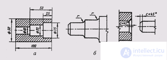
Fig. 285
the image with the applied dimensions gives a complete idea of their shape, therefore no images of the type of the left or top view are required. To clarify the individual elements used local cuts, sections, external elements.
Parts bounded by surfaces of rotation of different diameters are usually drawn so that the areas with larger diameters are to the left of the areas with smaller diameters, which corresponds to the location of the part on the wall during its processing (see Fig. 266).
If the part has internal coaxial rotation surfaces, then a frontal section is taken as the main image, which gives a complete picture of the part and facilitates dimensioning (Fig. 285, a). When this stage holes of large diameter have on the left.
When making drawings of parts with prevailing surface turning, the following requirements should be considered.
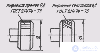
Fig. 286
1. In places of transition from one shaft diameter to another, fillets of fillets must be made (fig. 285, c).
2. For the convenience of assembling parts at the ends of the parts you need to chamfer (Fig. 285, b).
3. On the outer surfaces of the arms, heads, round nuts, screwed in manually, you need to perform the grooves according to GOST 21474-75 (Fig. 286). The corrugation symbol is applied directly on the part image on the leader line and includes the name, pitch and number of the standard.
4. If the surface of the part is being polished, then it is necessary to provide a special groove for the exit of the grinding wheel. Dimensions
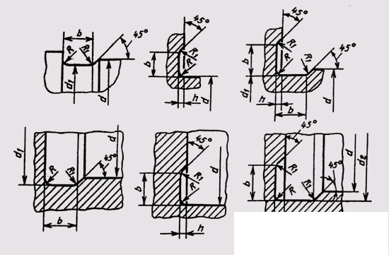
Fig. 287
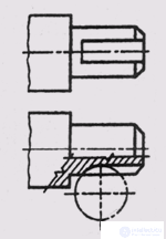
Fig. 288
grooves for round and flat grinding are defined by the standard. In fig. 287 shows images of grooves for grinding outer and inner diameters and recommendations for their sizes. The dimensions of the grooves in the dimensional chains of parts do not include.
If d = 10..15 mm, then b = 3 mm, d 1 = d + + 0.5 mm, h = 0.25 mm, R = 1 mm, R 1 = 0.5 mm.
If d = 50 ... 100 mm, then b = 5 mm, d 2 - d + + 1 mm, h = 0.5 mm, R = 1.5 mm, R 1 = 0.5 mm.
5. If the design of the part does not provide for free exit of the tool, then the transitional part of it in its shape and size should correspond to the shape and dimensions of this tool (fig. 288).
6. To install parts in the centers of the lathe in the parts perform center holes, the size and symbols of which are defined by the standard (Fig. 289).
7. External and internal grooves for cutting out the cutter when threading are drawn enlarged with the help of external elements (fig. 289).
In fig. 289 completed training drawing shaft. Section A - A reveals the dimensions of the cross section of the keyway, and section B - B gives the shape and dimensions of the prismatic part of the shaft. Center hole and keyway are shown by local incisions. Remote elements I and II help to determine the dimensions of the grooves for the metric thread and the depth of drilling under the locking screw.
When applying dimensions along the shaft, the right end of the part is taken as the main base. Regarding the auxiliary base, sizes 15, 36 and 70 mm are presented. The designation of surface roughness applied with regard to their design purpose.
Detail drawings except basic images of the finished part contain a full or partial scan of this part. Only dimensions that cannot be indicated on the finished part image are applied to the sweep image. Above the image of the scan put the inscription "Scan." Depict the scan of the solid main lines (Fig. 290). If necessary, fold out lines on the scan and make corresponding inscriptions. Particular attention should be paid to the correct determination of the dimensions at the bend points of the part.
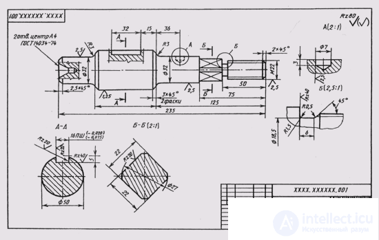
Fig. 289
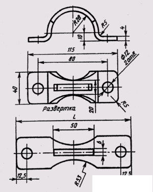
Fig. 290

Comments
To leave a comment
Descriptive Geometry and Engineering Graphics
Terms: Descriptive Geometry and Engineering Graphics