Lecture
Special connections include connections of parts gears, springs, etc. Gears constitute the most common group of mechanical gears and are used to convert and transfer rotary motion between shafts with parallel (cylindrical gears), intersecting (bevel gears) and intersecting (worm gears) axes , as well as to convert the rotational motion in the translational and vice versa (rack gear).
In a gear transmission, the transmission of motion is carried out by direct contact of the teeth of the wheel and gear. A gear wheel with a smaller number of teeth is called a gear, and with a larger number it is called a gear wheel. The main element of the gear are the teeth. In fig. 256 the image of a gear wheel with the indication of its elements, terms and designations is given. The diameters of the circles of the depressions
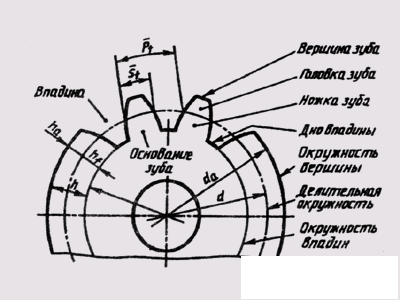
Fig. 256
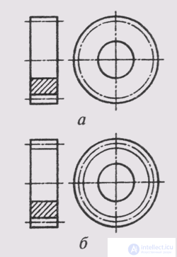
Fig. 257
df, the vertices d 3 and the pitch circle d are dependent on the number of teeth z and the pitch of the tangle P t . The engagement pitch is determined by the length of the arc of the pitch circle between the same points of two adjacent teeth. The length of the pitch circle is l d = zP 1 , whence the pitch circle diameter d = (P 1 / l ) z. Ratio P 1 / L — Called as a gear module, denoted by the letter t and measured in millimeters, i.e. t = P 1 / l, then d = mz. The module is the main parameter of the gear; its values are set by the ST SEV 310-76. Many sizes of gears depend on the size of the module. Usually, the height h of the tooth is taken equal to 2.25 t, while the height of the head h a of the tooth is taken equal to t, and the height of the h h of the tooth is 1 , 25 t . The diameter of the circle of vertices is d a = m (z + 2), the diameter of the circle of hollows is d f = m (z + 2.5).
Symbols of gears are determined by GOST 2.402-68.
The circles and the forming surfaces of the protrusions of the teeth are shown by solid main lines, the pitch circles are shown by dash-dotted thin lines, the circles and the forming surfaces of the tooth pits in the views are not shown or depicted as a solid thin line. In sections and sections forming surfaces on
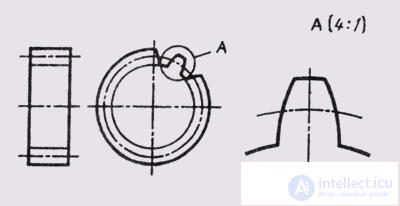
Fig. 258
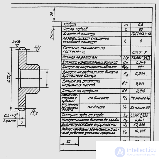
Fig. 259
throughout, they are represented by solid main lines (Fig. 257, a, b).
The teeth of gears are drawn only in axial cuts, conventionally combining them with the cutting plane, and are shown not dissected. If it is necessary to show the tooth profile, it is shown in a limited area of the wheel image or a remote element is used (Fig. 258).
Working drawings of gear spur wheels are made according to GOST 2.403-75. The drawing is placed an image of the gear and a table of parameters. On the image of the wheel put the data that is specified in the standard. On the image of a cylindrical gear (Fig. 259) indicate: the diameter of the circumference of the tops of the teeth, the width of the crown, the dimensions of the chamfers and the radii of rounding, the roughness of the surfaces of the peaks, hollows and side surface
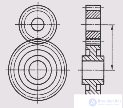
Fig. 260
teeth, and also put the dimensions of all structural elements of the part (rim, hub, wheel).
The parameter table is placed in the upper right corner of the drawing (in Fig. 259 the sizes of the graphs of the tables and their location are shown).
The parameter table in the drawing of a cylindrical gear wheel consists of three parts, separated from each other by solid main lines. The first (upper) part contains data for manufacturing, the second - for control, the third - reference data for the gear.
Working drawings of parts of gears of other types are carried out in accordance with the requirements of GOST 2.405-75 - GOST 2.406-76.
In the drawing gearing draw at least two images (Fig. 260). On the main view, the engagement may be shown in section. Then the drive wheel tooth is shown in front of the follower tooth. The contour of the visible tooth is drawn with solid main lines, and the contour of the invisible tooth - with dashed lines. In the drawing, the gearing is usually applied only one size - the size of the center distance. The rules of the symbols of the remaining data for transmissions of various types are determined by GOST 2402-68.
Springs are used to accumulate energy due to elastic deformation when exposed to an external load. With the termination of this load, the springs restore their original shape. According to the external form (Fig. 261), the springs are screw (cylindrical and conical) and non-screw (coil, lamellar, dish-shaped) springs. According to the type of deformation (or loading), there are springs of compression, tension, torsion and bending (flat springs).
In the cross section, the coils of the spring are either round (Fig. 261, a, b), or rectangular (Fig. 261, b, d, e) . The exact image of the springs is laborious and inexpedient. GOST 2.401—68 set
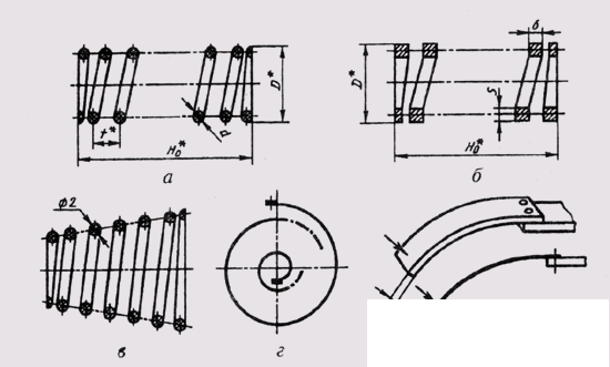
Fig. 261
Puts in conventional images and rules for drawing spring designs for all industries.
When depicting cylindrical springs (Fig. 261, a), the sections of the coils of the spring are conventionally depicted as circles, and the coils themselves are represented by straight lines. Extreme coils of the spring, working in compression, are not working, they are pressed and processed to ensure full adherence to the supporting surfaces. The remaining parts of the spring have a constant pitch, so the centers of the sections should be arranged in a checkerboard pattern. With a large number of turns, they are depicted only from the ends of the springs, passing the central part. An axial dash-dotted line is drawn through the center of the coil sections. The image of the coil springs in the drawing have horizontally. Springs are drawn in the free (unloaded) state. Springs, working in tension, are depicted without a gap between the coils.
In the drawings of springs with controlled power parameters, test charts are placed — a graph of the load from strain or strain from load (Fig. 262).
The working drawings depict springs only with the right winding. The direction of winding is indicated in the technical requirements, which are located under the image of the spring. Technical
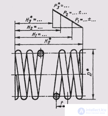
Fig. 262
Sky requirements must comply with GOST 2.401-68.
On the training drawings, it is enough to indicate the following data:
Dimensions for reference.
If the thickness of the spring material in the drawing is 2 mm or less, then the spring is represented by a solid main line with a thickness of 0.6 ... 1.5 mm (see. Fig. 261, d, d).

Comments