Lecture
Design documents for one-time use can be carried out in the form of sketches. A sketch is a drawing made without the use of a drawing tool (by hand) and the exact observance of the standard scale (in the visual scale). At the same time, the proportion in the sizes of the individual elements and the entire part as a whole should be maintained. The content of the sketches are the same requirements as the working drawings.
Sketches are performed in the following cases: when developing a new design, when drawing up a working drawing of an already existing part, if necessary, make a part according to the sketch itself.
It is recommended to perform sketches by hand on sheets of standard-sized checkered paper using a soft pencil TM, M or 2M. The sequence of the sketch in many respects coincides with the sequence
the accuracy of the performance drawing of the part. The sketch includes the following steps:
preparatory;
placement and drawing of images;
applying dimensions and signs of surface roughness of parts;
making the necessary inscriptions and finalizing the sketch.
At the preparatory stage, you need to carefully inspect the part, familiarize yourself with its design, determine the holes, grooves, grooves, tides, protrusions, chamfers and other elements present in it. Mentally divide the part into the simplest geometrical forms (cylinder, cone, prism, etc.) to determine how these forms are interconnected, put together.
Then you need to install the material from which the part is made, and the main technological operations (cutting, stamping, casting, etc.) that were used in the manufacture of the part. If possible, establish which part of the product is the part, what is its purpose in this product.
Then proceed to the selection of the main image of the part, taking into account some of the requirements of structural and technological order. The main image should give the most information about the details. Determine which sections or other images are advisable to complete to complement the main image. The number of images should be minimal, but sufficient to transfer the part forms.
Given the complexity of the part, its size and the size of a sheet of paper, decide on the choice of an approximate scale of the image in order to successfully arrange the working area of the sketch. Then proceed to drawing the image. To do this, first of all outline the axial and center lines of each image. Axial and center lines are carried out in order to identify either geometrical axes and centers, or project-planes of symmetry of a part. The lack of axial and center lines makes it difficult to understand the drawing, leads to the omission of the required dimensions, complicates the marking of parts. Then external contours of each image are applied (Fig. 291, a) with structural elements (chamfers, grooves, etc.), with thin lines marking the contours of the necessary cuts and sections. This takes into account that usually the inner surfaces are parallel to the outer surfaces of the part, the axes of the mounting holes are most often symmetrically located relative to the axes of the part or at the vertices of regular polygons; the sharp edges of the cast elements must be
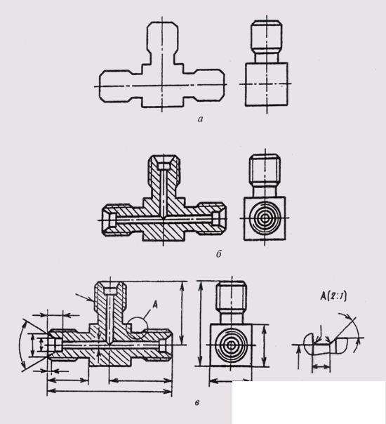
Fig. 291
rounded; constructive inclines and tapers should be reflected, despite their insignificance.
After checking the completed images, they remove the extra lines, perform hatching in sections and sections, and trace the visible contour of the images with a solid line (Fig. 291, b).
At the third stage of the sketch:
Outline dimensional bases and carry out extension and dimension lines for overall dimensions, inter-axial and intercenter dimensions and
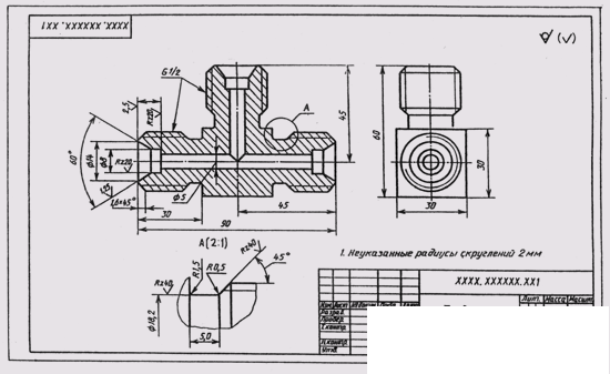
Fig. 292
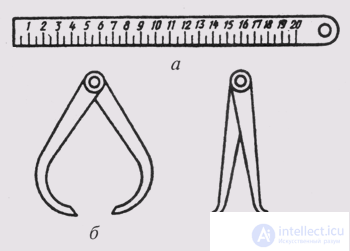
Fig. 293
their distances to the bases and for the sizes of individual elements of parts (Fig. 291, c);
measure the detail, compare the dimensions obtained by measurement with the dimensions recommended by the tables of size series, and put on the sketch adjusted, but close to the measured dimensions. At the same time, it is necessary to remember about the mating dimensions, which can be checked and refined according to the parts mated with this surface in the finished product;
determine the roughness of the surfaces of the part and put on the sketch of its symbols;
designate cuts, sections, portable elements.
The final stage includes checking the completed images, filling in the technical requirements and the master record on the sketch, as well as tables, if they are necessary (Fig. 292).
Measurement of parts when performing its sketch from life is performed using various tools that are selected depending on the size and shape of the part, as well as on the required accuracy of dimensioning.
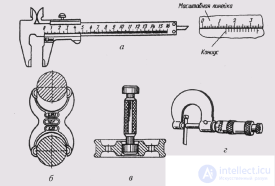
Fig. 294
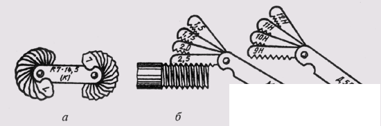
Fig. 295
A metal ruler (fig. 293, a), a caliper (fig. 293, b) and a caliper (fig. 293, c) measure external and internal dimensions with an accuracy of 0.1 mm. The caliper, limit bracket, caliber, micrometer allow you to perform a more accurate measurement (Fig. 294, a, b, c, d). Rounding radii are measured using radius templates (Fig. 295, a), and thread steps are measured using threaded templates (Fig. 295, b, c).
In fig. 296 shows how the linear dimensions of a part are measured with a ruler, caliper, and caliper.
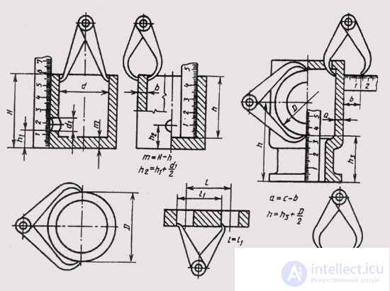
Fig. 296
According to the sizes of the external or internal diameter of the thread rto, the size of the thread pitch, determined by the threaded template, is selected the exact value of the thread according to the tables of standard threads.
If there is a discrepancy between the pitch and the diameter of the standard, then the thread is non-standard. In this case, you need to put on the detail sketch the thread pitch, the outer and inner diameters.

Comments