Lecture
When solving problems of engineering graphics, in some cases it becomes necessary to determine the actual size of a straight line segment. There are several ways to solve this problem: the method of a rectangular triangle, the method of rotation, plane-parallel movement, the replacement of planes of projections.
Let us consider an example of constructing an image of a segment to the true value in a complex drawing using the method of a right triangle. If the segment is located parallel to any of the planes of the projections, then on this plane it is projected in full size. If the segment is represented by a straight line of general position, then on one of the planes of the projections it is impossible to determine its true value (see Fig. 69).
Take a segment of general position AB (A ^ P 1 ) and construct its orthogonal projection on the horizontal plane of the projections (Fig. 78, a). In this case, a rectangle A 1 BB 1 is formed in which the segment itself is the hypotenuse, one leg is the horizontal projection of this leg, and the second leg is the difference of the height of points A and B of the leg. Since it is not difficult to determine the difference in the heights of the points of its segment by drawing a straight line, it is possible to construct a right-angled triangle along the horizontal projection of the segment (fig. 78, b) , taking the second leg to exceed one point over the second. The hypotenuse of this triangle will be the natural value of the segment AB.
A similar construction can be made on the frontal projection of the segment, only as the second leg it is necessary to take the difference in the depths of its ends (Fig. 78, c), measured on the plane P 1 .
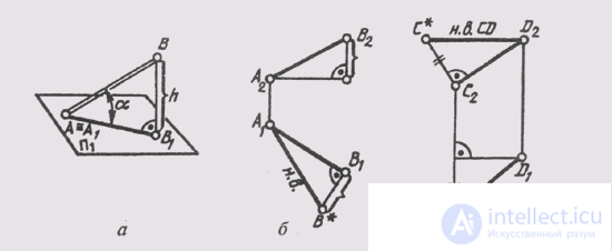
Fig. 78
To determine the actual size of a line segment, you can use its rotation relative to the planes of the projections so that it lies parallel to one of them (see § 36) or enter a new projection plane (replacing one of the projection planes) so that it is parallel to one of the projections of the segment ( see §§58, 59).

Comments
To leave a comment
Descriptive Geometry and Engineering Graphics
Terms: Descriptive Geometry and Engineering Graphics