Lecture
To construct a visual image of the object, we use axonometric projections (Ch. 12). You can execute it according to its complex drawing. Taking advantage of rice. 172, we will build
standard rectangular isometry of the object depicted on it. We use the reduced distortion coefficients. We take the location of the origin (point O) - in the center of the lower base of the object (Fig. 198). Having drawn the isometric axis and setting the scale of the image (M A 1.22: 1), we mark the centers of the circles of the upper and lower bases of the cylinder, as well as the circles bounding the T-shaped notch. We draw ellipses that are an isometry of circles (see § 77). Then draw lines parallel to the coordinate axes that limit the cutout in the cylinder. Isometry of the line of intersection of a through cylindrical hole, whose axis
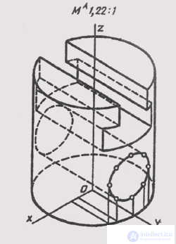
Fig. 198
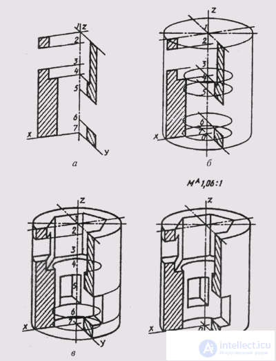
Fig. 199
parallel to the axis Oy with the surface of the main cylinder, we construct at separate points using the same points (K, L, M and symmetric to them) as in the construction of the left view. Then we delete the auxiliary lines and finally outline the image, taking into account the visibility of individual parts of the object.
To construct an axonometric image of the object, taking into account the cut, we use the conditions of the problem, the solution of which is shown in Fig. 185, a. On a given drawing for constructing a visual image, we note the position of the projections of the coordinate axes and on Oz soybeans, we note the centers 1,2, ..., 7 of the object's figures located in horizontal planes G 1 ', T " 2 , ..., G 7 ', This is the upper and lower base of the object, the base of the internal holes .
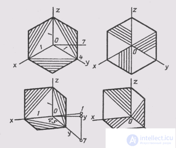
Fig. 200
The flat figures obtained in this case are already built on a complex drawing, since they are the halves of the frontal and profile section of objects (Fig. 185, b).
The construction of a visual image begins with the axes of dimetry and an indication of the scale М А 1.06: 1 (see § 78). On the z axis, mark the position of the centers 1, 2, ..., 7 (Fig. 199, a); we take the distances between them from the main view of the object. Through the marked points we draw the dimetry axis. Then, in dimetry, we build section figures, first in the xOz plane , and then in the yOz plane . We take the sizes of coordinate segments from the complex drawing (fig. 185); at the same time, the dimensions along the y axis are halved. Perform shading sections. The angle of inclination of the hatching lines in axonometry is determined by the diagonals of the parallelograms built on axonometric axes, taking into account the distortion factors. In fig. 200, and an example is given of choosing the direction of hatching in isometric, and in fig. 200, b - in dimetry. Next, we build ellipses - dimetry of circles located in horizontal planes (see. Fig. 199, b). We draw the contour lines of the outer cylinder, internal vertical holes, build the base of these holes (Fig. 199, c); draw the visible lines of intersection of the horizontal holes with the outer and inner surfaces.
Then we delete the auxiliary construction lines, check the correctness of the drawing and draw the drawing with the lines of the required thickness (Fig. 199, d).

Comments
To leave a comment
Descriptive Geometry and Engineering Graphics
Terms: Descriptive Geometry and Engineering Graphics