Lecture
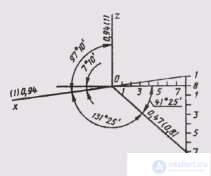
Rectangular dimetry is characterized by the fact that the distortion coefficients determined from the expression (1), and = w = 0.94, av = 0.47. They are defined as follows:
u 2 + (u / 2) 2 + u 2 = 2;
u 2 = 8/9; u = w = (8/9) 1/2 = 0.94; v = 0.47.
In accordance with GOST 2.317-69, practical constructions in rectangular dimetry should be performed using the reduced distortion coefficients: u = w = 1 and v = 0.5.
The arrangement of the axes of standard rectangular dimetry is shown in fig. 162. The axonometric scale for rectangular dimetry will be M A 1,06: 1.
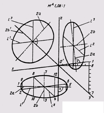
In rectangular dimetry, equal circles of diameter d, lying in the coordinate planes xOy and yo, are projected into equal ellipses, the major axis of which is 2a = 1.06d, and the minor axis 2b = 0.35d , if we use the reduced distortion factors. A circle located in the xOz plane is projected into an ellipse with the axes: the major axis of which is 2a 1 = 1.066d, the minor axis - 2b 1 = 0.95d (Fig. 163). Diameters

Fig. 162

Fig. 163

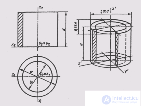
Fig. 164
Nosti, parallel to the coordinate axes, are projected into segments, parallel to the axes of diametry l 1 = l 2 = d; l = 0.5d, with || Oh; l 2 || OU; l 3 || Oz.
In addition to the points indicated, it is possible to build four more points symmetrical to the points bounding the projections of diameters parallel to the coordinate axes. Then an ellipse, like the dimetry of a circle, can be constructed from its twelve points.
The image of geometric surfaces in rectangular diameter will be considered on the example of constructing a standard rectangular dimetry of a straight circular cylinder. In fig. 164 shows an example of a complex drawing of a hollow cylinder of height H with outside d and inside d1 diameters. We will arrange the cylinder in its natural size in the natural coordinate system Oxyz, relative to which we will build its dimetric projection. As in the case of the construction of circles in isometry, in dimetry we also begin the construction of a figure with ellipses of the upper and lower bases of the cylinder, which are isometric projections of the circles of these bases. The base circles are located in planes parallel to the horizontal plane of the projections, therefore, using the rules given earlier, we determine that the major axes of the ellipses will be perpendicular to the axis Oz. The minor axes of the ellipses will coincide with the direction of the axis Oz. The centers of the axes of the ellipses of the lower and upper bases are located at a distance I. The values of the axes are determined depending on the size of the outer and inner diameters of the cylinders. Constructing ellipses, we will give sketch lines tangent to external ellipses.
For clarity, we construct a cutout of a quarter of a cylinder, the construction of which can be seen from Fig. 164. We select the direction of the hatching of the cut, as shown in Fig. 200. Invisible lines show dashed lines. For clarity, the same lines show the line cut part of the cylinder. Visible contour lines suggest the desired thickness.
Comments
To leave a comment
Descriptive Geometry and Engineering Graphics
Terms: Descriptive Geometry and Engineering Graphics