
Lecture
Formula (1.12a) represents Ohm's law for a branch of a circuit (or diagram) with an EMF source (generalized Ohm's law).
If, as a result of calculation using (1.12a), the current turns out to be negative, this means that the actual direction of the current does not coincide with the chosen positive direction (it is opposite to the arbitrarily chosen direction).
For the voltage between any two points of a circuit, a positive direction can likewise be chosen arbitrarily. The positive direction of the voltage is indicated by subscripts on the letter U or is shown on diagrams by an arrow, which, for example, for the voltage  we will henceforth draw from point a to point b. Thus, the voltage, like the current, must be treated as an algebraic quantity in calculations.
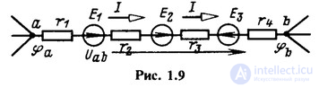

For the EMFs of voltage sources and the currents of current sources, if their actual directions are unknown, arbitrary positive directions are likewise chosen, which are indicated by double subscripts or shown by arrows.
In sections of the circuit with passive elements, we will always choose the positive directions of voltage and current to coincide. In this case, a separate arrow for the voltage need not be drawn.
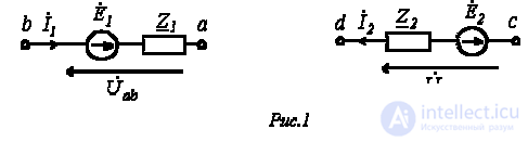
Let us take two branches of a circuit a-band c-d (see Fig. 1) and write equations for them in complex form, taking into account the positive directions of the voltages and currents shown in Fig. 1.
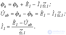
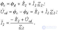
Combining both cases, we obtain
 |
(1) |
or for direct current
 . . |
(2) |
Formulas (1) and (2) are the analytical expression of Ohm's law for a branch with an EMF source, according to which the current in the branch with an EMF source equals the algebraic sum of the voltage across the terminals of the branch and the EMF, divided by the resistance of the branch. In the case of alternating current, all the quantities mentioned are complex numbers. Here, the EMF and voltage are taken with a “+” sign if their direction coincides with the chosen direction of the current, and with a “-” sign if their direction is opposite to the direction of the current.
The calculation of sinusoidal alternating-current circuits can be carried out not only by constructing phasor diagrams but also analytically – by performing operations with complex numbers that symbolically represent the sinusoidal EMFs, voltages, and currents. The advantage of phasor diagrams is their clarity; their drawback is the low accuracy of graphical constructions. The use of the symbolic method makes it possible to calculate circuits with a high degree of accuracy.
The symbolic method for calculating sinusoidal-current circuits is based on Kirchhoff's laws and Ohm's law in complex form.
Equations expressing Kirchhoff's laws in complex form have exactly the same appearance as the corresponding equations for direct-current circuits. Only the currents, EMFs, voltages, and resistances enter the equation as complex quantities.
1. Kirchhoff's first law in complex form:
 . . |
(3) |
2. Kirchhoff's second law in complex form:
 |
(4) |
or, as applied to equivalent circuits with EMF sources
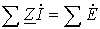 . . |
(5) |
3. Accordingly, the matrix form of Kirchhoff's laws in complex form is:
§ Kirchhoff's first law:
. ; ; |
(6) |
§ Kirchhoff's second law
 . . |
(7) |
Example.
Given:
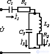
Fig. 2
 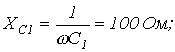  |
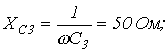   |
| Find: 1) the total complex impedance of the circuit  ; ;2) the currents  |
Solution:
1.  .
.
2.  .
.
3. 
 .
.
4. Taking the initial phase of the voltage as zero, we write:
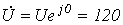 .
.
Then
 .
.
5. Since the current is distributed inversely proportional to the resistance of the branches (this follows from Ohm's law), then

6.  .
.
7. A similar result can be obtained by writing, for this circuit, the equations according to Kirchhoff's laws in complex form
 |
 |
or after substituting the numerical values of the circuit parameters
The operating mode of any circuit is fully characterized by equations formulated on the basis of Kirchhoff's laws. In this case it is necessary to set up and solve a system with n unknowns, which can turn out to be a very laborious task for a large number n of circuit branches. However, the number of equations to be solved can be reduced by using special calculation methods, which include the mesh-current method and the node-potential method.
The idea of the mesh-current method is that equations are formulated only from Kirchhoff's second law, but not for the actual currents, rather for imaginary currents circulating around closed loops, i.e., when the principal loops are chosen equal to the currents of the link branches. The number of equations equals the number of independent loops, i.e., the number of link branches of the graph  . Kirchhoff's first law is satisfied automatically. The loops can be chosen arbitrarily, as long as their number equals
  and each new loop contains at least one branch not included in the previous ones. Such loops are called independent. Their selection is facilitated by using the topological concepts of the tree and the link branches.
The directions of the actual and the loop currents are chosen arbitrarily. The choice of positive directions before beginning the calculation need not determine the actual directions of the currents in the circuit. If, as a result of the calculation, any of the currents, as with the use of equations from Kirchhoff's laws, comes out with a “-” sign, this means that its true direction is opposite.
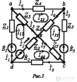
Let us consider the circuit shown in Fig. 3.
Let us express the branch currents in terms of the loop currents:
 ;
;
 ;
; 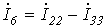 ;
;
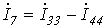 ;
;  .
.
Going around the loop aeda, by Kirchhoff's second law we have
 .
.
Since  ,
,
then
 .
.
Thus, we have obtained the equation for the first loop in terms of the loop currents. Similarly, equations can be written for the second, third, and fourth loops:
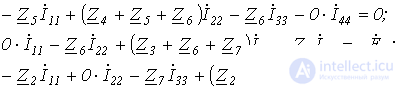
and, together with the first, solve them for the loop currents, then find the branch currents from the equations relating the loop currents to the branch currents.
However, this system of equations can also be written in a formal way:
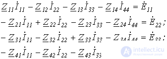
When writing these equations, the following must be kept in mind:
 - the sum of the resistances contained in the i-th loop;
 - the sum of the resistances common to the i-th and k-th loops, where
  ;
;
the terms on the main diagonal are always written with a “+” sign;
a “+” sign is placed before the remaining terms if, through the common resistance  the i-th and k-th loop currents pass in the same direction; otherwise a “-” sign is placed;
if the i-th and k-th loops have no common resistances, then  ;
;
the right-hand side of the equations contains the algebraic sum of the EMFs included in the loop: with a “+” sign if the direction of the EMF coincides with the chosen direction of the loop current, and with a “-” sign if it does not.
In our case, for the first equation of the system, we have:

It should be noted that, since  , the coefficients of the loop equations are always symmetric about the main diagonal.
If the circuit contains current sources in addition to EMF sources, they are taken into account in the left-hand sides of the equations as known loop currents: the k-th loop current flowing through the branch containing the k-th current source equals this current  .
.
This method follows from Kirchhoff's first law. The node potentials are taken as the unknowns; once their values have been found, the branch currents are then determined using Ohm's law for a branch containing an EMF source. Since potential is a relative quantity, the potential of one of the nodes (any one) is taken as zero. Thus, the number of unknown potentials, and hence the number of equations, equals  , i.e., the number of tree branches
  .
.
Let us consider the circuit shown in Fig. 4, in which we take  .
.
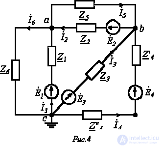
Suppose that  and
and  are known. Then the current values, on the basis of Ohm's law for a branch with an EMF source,
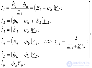
Let us write the equation by Kirchhoff's first law for node a:

and substitute the values of the currents entering it, determined above:
 .
.
Grouping the corresponding terms, we obtain:
 .
.
Similarly, we can write for node b:
 .
.
As with the loop-current method, the system of equations for the node-voltage method can be written in a formal way. In doing so, the following rules must be followed:
1. The left-hand side of the i-th equation contains, with a “+” sign, the potential  of the i-th node, for which this i-th equation is written, multiplied by the sum of the conductances
  of the branches connected to this i-th node, and, with a “-” sign, the potentials
  of the adjacent nodes, each multiplied by the sum of the conductances
  of the branches connected to the i-th and k-th nodes.
It follows from the above that all the terms  , standing on the main diagonal in the left-hand side of the system of equations, are written with a “+” sign, while all the others are written with a “-” sign, where
  . This last equality, by analogy with the loop-current method, ensures that the coefficients of the equations are symmetric about the main diagonal.
2. The right-hand side of the i-th equation contains the so-called node current  , equal to the sum of the products of the EMFs of the branches meeting at the i-th node and the conductances of these branches. Here a term of the sum is written with a “+” sign if the corresponding EMF is directed toward the i-th node; otherwise a “-” sign is placed. If the branches meeting at the i-th node contain current sources, the signs of the currents of these current sources, entering the node current as simple terms, are determined in the same way.
In conclusion, note that the choice of one method or another is determined by what needs to be found, as well as by which method gives a lower order for the system of equations. When calculating currents with an equal number of equations, it is preferable to use the loop-current method, since it does not require additional calculations using Ohm's law. The node-voltage method is very convenient for calculating multiphase circuits, but is inconvenient for calculating circuits with mutual inductance.
1. In the branch shown in Fig. 1, 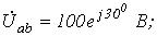
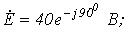
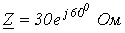 . Determine the current
  .
.
Answer: 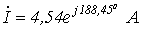 .
.
2. What is the essence of the symbolic (phasor) method for calculating sinusoidal-current circuits?
3. What is the essence of the loop-current method?
4. What is the essence of the node-voltage method?
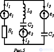
5. In the circuit shown in Fig. 5,  ;
;  ;
;
 ;
; 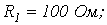
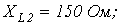
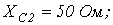
 . Using the loop-current method, determine the complex rms values of the branch currents.
Answer: 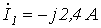 ;
;  ;
;  .
.
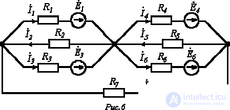
6. In the circuit shown in Fig. 6, 
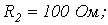

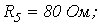
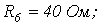
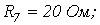


 . Calculate the branch currents using the node-voltage method.
Answer:  ;
;  ;
;  ;
;  ;
;  ;
;  ;
;  .
.

Comments