
Lecture
Transposition in electrical engineering — changing the relative arrangement of the conductors of individual phases along the length of an overhead power transmission line to reduce the undesirable influence of power lines on each other and on nearby communication lines.
Conductor transposition – changing the spatial position of the conductors in order to equalize their length and, correspondingly, their coupling with the electromagnetic field. When winding is performed without transposition, significant energy losses are observed. In a continuous winding, all the conductors being laid change places when moving from one coil to another. In this case the number of transitions must equal the number of conductors laid in parallel. In manufacturing plants, when winding continuous windings, a rule is used according to which the beginning and end of a coil is taken to be the turn consisting of an odd number of parallel conductors. Conductor transposition is widely used when winding helical windings for power oil-filled transformers of the TMG, TMN, and TM types. This makes it possible to substantially reduce losses in the transformer itself and reduces the probability of inter-turn short circuits.
In order to make the capacitance and inductance of all three phases of the circuit equal, conductor transposition is applied on the power line, i.e., the conductors' relative positions are mutually interchanged, with each phase conductor covering one third of the route (Fig. 3). One such triple shift is called a transposition cycle.
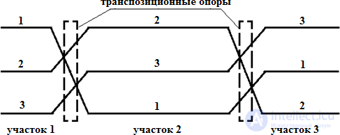
Fig. 3. Diagram of a complete transposition cycle of overhead power line sections: 1, 2, 3 – phase conductors
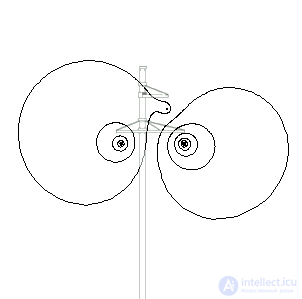
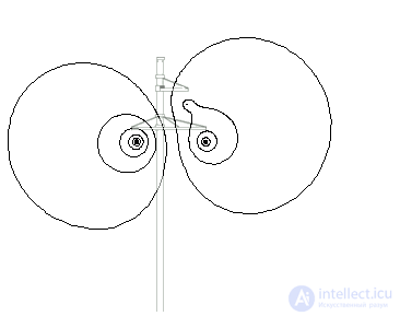
Transposition of the phase conductors of an overhead power line with bare conductors is applied at voltages of 110 kV and above and for line lengths of 100 km or more. One of the options for mounting the conductors on a transposition tower is shown in Fig. 4. It should be noted that transposition of current-carrying cores is sometimes applied in cable lines as well; moreover, modern technologies for designing and building overhead lines make it technically possible to control the line parameters (controlled self-compensating lines and compact ultra-high-voltage overhead lines).
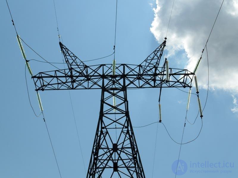
Fig. 4. Transposition tower
The conductors and overhead ground wires of the line must be rigidly secured at certain points on the tension insulators of anchor towers (terminal towers 1 and 7, installed at the beginning and end of the line, as shown in Fig. 5) and tensioned to the specified tension. Between the anchor towers, intermediate towers are installed to support the conductors and ground wires, using suspension insulator strings with suspension clamps, at a specified height (towers 2, 3, 6), installed along the straight section of the line; angle towers (towers 4 and 5), installed at route turns of the line; and crossing towers (towers 2 and 3), installed at the span where the overhead line crosses some natural obstacle or engineering structure, for example a railway or a highway.
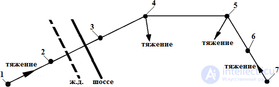
Fig. 5. Sketch of an overhead power transmission line
The distance between anchor towers is called the anchor span of the overhead power line (Fig. 6). The horizontal distance between the conductor attachment points on adjacent towers is called the span length L. A sketch of the line span is shown in Fig. 7. The span length is chosen mainly based on economic considerations, except for crossing spans, taking into account both the height of the towers and the sag of the conductors and ground wires, as well as the number of towers and insulators along the entire length of the line.
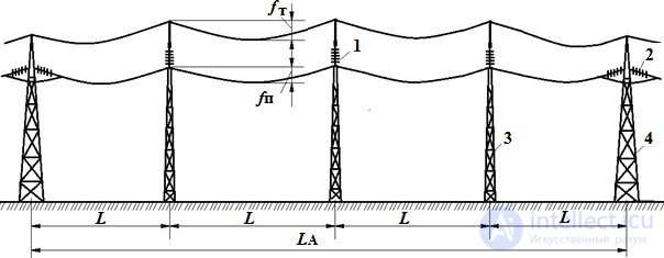
Fig. 6. Sketch of an anchor span of the line: 1 – suspension insulator string; 2 – tension insulator string; 3 – intermediate tower; 4 – anchor tower
The smallest vertical distance from the ground to the conductor at its greatest sag is called the ground clearance of the line – h. The ground clearance must be maintained for all rated voltages, taking into account the risk of air-gap flashover between phase conductors and the highest point of terrain. The ecological aspects of the effect of high electromagnetic field strengths on living organisms and plants must also be taken into account.
The greatest deflection of a phase conductor fph or of an overhead ground wire fgw from the horizontal under the effect of a uniformly distributed load from its own weight, ice weight, and wind pressure is called the sag. To prevent conductor clashing, the sag of the ground wire is made 0.5 – 1.5 m less than the sag of the conductor.
A section of a 110 kV class overhead power line, 120 kilometers long.
Problem type:
Plane-parallel magnetic field problem for alternating currents.
Geometry:
ABCGround 2 m 3.5 m 2 m 3 m 14.5 m 3 m
Bare conductor for overhead power lines, type AC
SteelAluminum
Transposition scheme. Line length l = 120 km.
ABCCABBCA40 km 40 km 40 km
Given:
|
Rated (rms) line voltage Ul = 110 kV |
 |
Task:
Determine the inductance of a phase of the power line.
Solution:
According to the PUE (Electrical Installation Code), on overhead lines of 110-500 kV and longer than 100 km, one complete transposition cycle must be performed to limit current and voltage asymmetry. The transposition step is not standardized with respect to its effect on communication lines. In this case the transposition must be carried out so that the total lengths of the line sections with different phase orderings are approximately equal.
The length of our line is 120 km, and a complete transposition cycle of the line conductors occurs over the entire transmission section. The distance between transposition points (transposition towers) is 40 km.
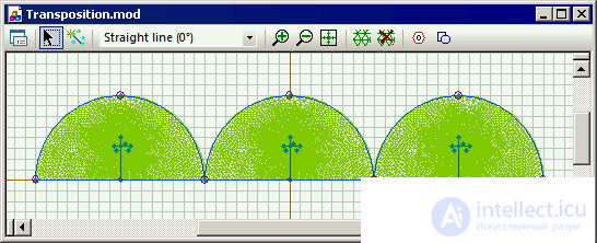
To account for the different arrangement of the line sections, they were all added to the model. The sections were magnetically isolated and did not interfere with each other, but were connected in the circuit. In this way it was possible to account for the different conductor arrangement within a single problem.
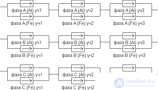
The total impedance of the line is made up of the impedances of the individual sections and can be found as the voltage drop across the individual sections divided by the current:
Zl = (U1 + U2 + U3) / I.
The line impedance can be represented as the sum of the resistance (R) and the reactance (Xl):
Zl = Rl + j·Xl.
To determine the line inductance we use Ohm's law and the relationship between reactance and inductance:
L = Xl / 2 π f,
where Xl - reactance of the line phase;
f - current frequency.
Calculation results:
Table of measured currents and voltages for phase A
| Section 1 | Section 2 | Section 3 | Total | |
| Voltage UA, V | 7915 + j4249 | 8288 + j4192 | 8632 + j3470 | 24834 + j11911 |
| Voltage UB, V | -7329 + j5744 | -7637 + j4732 | -7781 + j5084 | -22747 + j15559 |
| Voltage UC, V | -513 - j9270 | -1310 - j9211 | -277 - j8982 | -2101 - j27462 |
| Current IA, A |
370 - j387 |
370 - j387
|
||
| Current IB, A |
150 + j514 |
150 + j514
|
||
| Current IC, A |
-520 - j127 |
-520 - j127
|
||
| Impedance ZA, Ohm |
|
16.0 + j48.9
|
||
| Impedance ZB, Ohm |
|
16.0 + j48.9
|
||
| Impedance ZC, Ohm |
|
16.0 + j48.9
|
Phase inductance: Lph = LA = LB = LC = 0.156 H (over 120 km).
See also
[[b8489]]

Comments