
Lecture
A three-phase circuit is a special case of polyphase electrical systems, which are a set of electrical circuits in which EMFs of the same frequency act, shifted in phase relative to one another by a certain angle. Note that these EMFs are usually, primarily in power engineering, sinusoidal. However, in modern electromechanical systems, where frequency converters are used to control actuator motors, the voltage system is in general non-sinusoidal. Each part of a polyphase system, characterized by the same current, is called a phase, i.e. a phase is a section of the circuit belonging to the corresponding winding of the generator or transformer, the line, and the load.
Thus, the term "phase" has two different meanings in electrical engineering:
The development of polyphase systems was historically conditioned. Research in this area was driven by the demands of developing industry, and the success in the development of polyphase systems was aided by discoveries in the physics of electrical and magnetic phenomena.
The most important prerequisite for the development of polyphase electrical systems was the discovery of the rotating magnetic field phenomenon (G. Ferraris and N. Tesla, 1888). The first electric motors were two-phase, but they had low performance characteristics. The three-phase system proved to be the most rational and promising, and its main advantages will be discussed further below. A great contribution to the development of three-phase systems was made by the outstanding Russian electrical engineer M.O. Dolivo-Dobrovolsky, who created three-phase induction motors and transformers and proposed three- and four-wire circuits, and who is rightly considered the founder of three-phase systems.
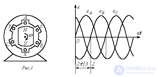
The source of three-phase voltage is a three-phase generator, on whose stator (see Fig. 1) a three-phase winding is placed. The phases of this winding are arranged so that their magnetic axes are shifted in space relative to one another by  electrical radians. In Fig. 1 each stator phase is conventionally shown as a single turn. The starts of the windings are conventionally denoted by the capital letters A, B, C, and the ends, respectively, by the lowercase letters x, y, z. EMFs in the stationary stator windings are induced as a result of their turns being cut by the magnetic field created by the current in the field winding of the rotating rotor (in Fig. 1 the rotor is conventionally shown as a permanent magnet, which is used in practice at relatively low power levels). As the rotor rotates at a uniform speed, periodically varying sinusoidal EMFs of the same frequency and amplitude are induced in the stator phase windings, differing from one another in phase, due to the spatial shift, by
  radians (see Fig. 2).
Three-phase systems are now the most widespread. All major power plants and consumers operate on three-phase current, which is due to a number of advantages of three-phase circuits over single-phase ones, the most important of which are:
- economical transmission of electrical energy over long distances;
- the most reliable and economical motor satisfying the requirements of industrial electric drives is the squirrel-cage induction motor;
- the possibility of obtaining, by means of stationary windings, a rotating magnetic field, which underlies the operation of synchronous and induction motors, as well as a number of other electrical devices;
- the balanced nature of symmetrical three-phase systems.
To examine the most important property of balance in a three-phase system, which will be proved further below, let us introduce the concept of symmetry of a polyphase system.
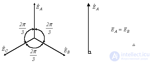
A system of EMFs (voltages, currents, etc.) is called symmetrical if it consists of m vectors of EMF (voltage, current, etc.) equal in magnitude, shifted in phase relative to one another by the same angle  . In particular, the phasor diagram for the symmetrical EMF system corresponding to the three-phase system of sinusoids in Fig. 2 is shown in Fig. 3.
 |
|
| Fig.3 | Fig.4 |
Among asymmetrical systems, the two-phase system with a 90-degree phase shift is of the greatest practical interest (see Fig. 4).
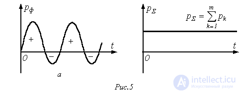
All symmetrical three-phase and m-phase (m>3) systems, as well as the two-phase system, are balanced. This means that although the instantaneous power in individual phases pulsates (see Fig. 5,a), changing over the course of one period not only in magnitude but, in general, also in sign, the total instantaneous power of all phases remains constant throughout the entire period of the sinusoidal EMF (see Fig. 5,b).
Balance is of the utmost practical importance. If the total instantaneous power were to pulsate, a pulsating torque would act on the shaft between the turbine and the generator. Such a variable mechanical load would adversely affect the power-generating unit, shortening its service life. The same considerations apply to polyphase electric motors.
If symmetry is disturbed (the Tesla two-phase system, due to its specific nature, is not taken into account here), balance is disturbed as well. That is why, in the power industry, strict attention is paid to keeping the generator load symmetrical.
Connection schemes of three-phase systems
A three-phase generator (transformer) has three output windings, equal in number of turns, but developing EMFs shifted in phase by 120°. It would be possible to use a system in which the phases of the generator winding are not galvanically connected to one another. This is the so-called unconnected system. In this case, each generator phase would have to be connected to the receiver by two wires, i.e. there would be a six-wire line, which is uneconomical. For this reason, such systems have not become widespread in practice.
To reduce the number of wires in the line, the generator phases are galvanically connected to one another. Two types of connection are distinguished: star (wye) and delta. In turn, with a star connection the system can be three-wire or four-wire.
Star connection
Fig. 6 shows a three-phase system with the generator and load phases connected in a star. Here the wires AA’, BB’ and CC’ are the line wires.
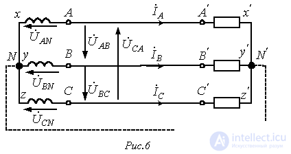
A line wire is a wire connecting the starts of the phases of the generator winding and the receiver. The point at which the ends of the phases are connected into a common node is called the neutral point (in Fig. 6, N and N’ are, respectively, the neutral points of the generator and the load).
The wire connecting the neutral points of the generator and the receiver is called the neutral wire (shown dashed in Fig. 6). A three-phase system with a star connection without a neutral wire is called three-wire; with a neutral wire, four-wire.
All quantities relating to the phases are called phase variables, and those relating to the line are called line variables. As can be seen from the diagram in Fig. 6, with a star connection the line currents  and
and  equal the corresponding phase currents. When a neutral wire is present, the current in the neutral wire is
 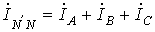 . If the system of phase currents is symmetrical, then
  . Consequently, if the symmetry of the currents were guaranteed, the neutral wire would not be needed. As will be shown further below, the neutral wire ensures that the symmetry of the voltages across the load is maintained when the load itself is asymmetrical.
Since the voltage at the source is opposite in direction to its EMF, the phase voltages of the generator (see Fig. 6) act from points A, B and C to the neutral point N;  are the phase voltages of the load.
Line voltages act between the line wires. In accordance with Kirchhoff's second law, for the line voltages we can write
 ; ; |
(1) |
 ; ; |
(2) |
 . . |
(3) |
Note that always  - as the sum of voltages around a closed loop.
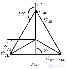
Fig. 7 shows the phasor diagram for a symmetrical system of voltages. As its analysis shows (the rays of the phase voltages form the sides of isosceles triangles with base angles equal to 30°), in this case
 |
(4) |
Usually in calculations it is assumed that  . Then, for the case of direct phase sequence,
 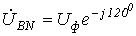 ,
,  (with reverse phase sequence, the phase shifts of
  and
and  are swapped). Taking this into account, on the basis of relations (1)…(3), the complexes of the line voltages can be determined. However, when the voltages are symmetrical, these quantities are easily determined directly from the phasor diagram in Fig. 7. Directing the real axis of the coordinate system along the vector
  (whose initial phase equals zero), we read off the phase shifts of the line voltages relative to this axis, and determine their magnitudes in accordance with (4). Thus for the line voltages
  and
and  we obtain:
 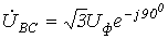 ;
; 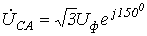 .
.
Delta connection
Since a significant part of the receivers connected into three-phase circuits are asymmetrical, in practice, for example in circuits with lighting fixtures, it is very important to ensure the independence of the operating modes of the individual phases. Besides the four-wire circuit, three-wire circuits with the receiver phases connected in a delta also have this property. But the generator phases can also be connected in a delta (see Fig. 8).
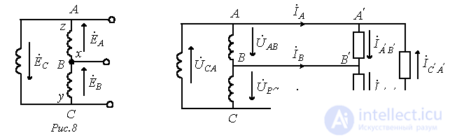
For a symmetrical system of EMFs we have
 .
.
Thus, in the absence of a load on the generator phases, in the circuit of Fig. 8 the currents will be zero. However, if the start and end of any phase are swapped, then  and a short-circuit current will flow in the delta. Consequently, for a delta connection the order of connecting the phases must be strictly observed: the start of one phase is connected to the end of another.
The circuit for connecting the generator and load phases in a delta configuration is shown in Fig. 9.
It is evident that in a delta connection, the line voltages equal the corresponding phase voltages. By Kirchhoff's first law, the relationship between the line and phase currents of the load is determined by the relations
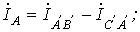
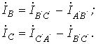
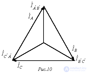
The line currents can be expressed in terms of the generator's phase currents in a similar way.
Fig. 10 shows the phasor diagram of a symmetrical system of line and phase currents. Its analysis shows that under symmetrical currents
 . . |
(5) |
Finally, we note that besides the «star-star» and «delta-delta» connections considered above, «star-delta» and «delta-star» schemes are also used in practice.
References
Review Questions and Problems
 . Determine the complexes of the remaining phase and line currents.
Comments