
Lecture
The input impedance of a long line (a distributed-parameter circuit) is defined as the lumped impedance whose connection in place of the line at the source terminals does not change the operating mode of the latter.
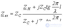
In the general case, for a line with an arbitrary load  , for the input impedance we can write
 . . |
(1) |
The expression obtained shows that the input impedance is a function of the line parameters  and
and  , its length
  , and the load
  . At the same time, the dependence of the input impedance on the length of the line, i.e., the function
  , is not monotonic but has an oscillatory character caused by the influence of the backward (reflected) wave. As the length of the line increases, both the forward and, correspondingly, the reflected waves attenuate more and more strongly. As a result, the influence of the latter weakens and the amplitude of oscillation of the function
  decreases.
For a matched load, i.e., at  , as was shown earlier, there is no backward wave, which fully corresponds to expression (1), which at
  transforms into the relation
 .
.
The input impedance at  is determined by the same value.
For certain values of the line length, its input impedance may turn out to be purely resistive. The length of the line at which  is real is called resonant. As in a lumped-parameter circuit, resonance is most clearly observed in the absence of losses. For a lossless line, on the basis of (1), we can write
 . . |
(2) |
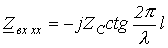
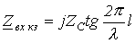
From (2), for the open-circuit (OC) and short-circuit (SC) modes, i.e., cases in which the active power consumed by the load is zero, we respectively obtain:
 ; ; |
(3) |
 . . |
(4) |
A study of how  varies with the length
  of the line, on the basis of (3), shows that at
 varies in magnitude within
  and has a capacitive character, while at
  it varies within
  and has an inductive character. This alternation continues further, at intervals of line length equal to a quarter wavelength (see Fig. 1,a).
In accordance with (4), the dependence  at SC will have a similar character, but shifted by a quarter wavelength (see Fig. 1,b).
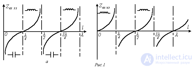
Points where  correspond to voltage resonance, and points where
  correspond to current resonance.
Thus, by varying the length of a lossless line, capacitive and inductive reactances of any magnitude can be simulated. Since the wavelength  is a function of frequency, a similar change in
  can be achieved not by changing the length of the line but the frequency of the generator. At certain frequencies, the input impedance of a distributed-parameter circuit also becomes real. Such frequencies are called resonant. Thus, resonant frequencies are those at which an integer number of quarter-wavelengths fits along the line.
Transient processes in distributed-parameter circuits
Transient processes in distributed-parameter circuits have the character of traveling (wandering) waves propagating through the circuit in various directions. These waves can undergo multiple reflections from the junctions of different lines, from nodal points where loads are connected, and so on. As a result of the superposition of these waves, the picture of the processes in the circuit can turn out to be quite complex. In this process, overcurrents and overvoltages hazardous to equipment may arise.
Transient processes in circuits with distributed parameters arise from various changes in their operating conditions: switching a load or energy sources on or off, connecting new line sections, and so on. Lightning discharges can also be a cause of transient processes in long lines.
Equations of transient processes in circuits with distributed parameters
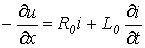
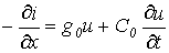
When considering the equivalent circuit of a distributed-parameter circuit, partial differential equations were obtained
 ; ; |
(5) |
 |
(6) |
Integrating them with losses taken into account is a fairly complex task. For this reason, we will treat the circuit as a lossless line, i.e., we set  and
and  . This assumption is valid for lines with small losses, as well as when analyzing the initial stages of transient processes, which are often the most significant with respect to overvoltages and surge currents.
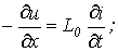
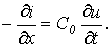
Taking this into account, from relations (5) and (6) we proceed to the equations
 |
(7) |
 |
(8) |
To obtain equation (7) in terms of a single variable, we differentiate (7) with respect to x, and (8) – with respect to t:
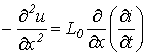 ; ; |
(9) |
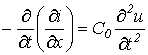 . . |
(10) |
Given that for a lossless line 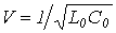 , after substituting relation (10) into (9) we obtain
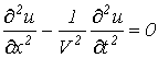 . . |
(11) |
The equation for the current is obtained similarly
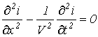 . . |
(12) |
The wave equations (11) and (12) are satisfied by the solutions
 ;
;
 .
.
As before, the forward and backward voltage and current waves are related to each other by Ohm's law for waves
 and
and 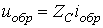 ,
,
where 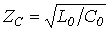 .
.
When calculating transient processes, one should remember:
As already noted, the transient process in circuits with distributed parameters is characterized by the superposition of multiply reflected waves. Let us consider multiple reflections for the two most characteristic cases: connecting a DC voltage source to an open-circuited line and to a short-circuited line.
Transient processes when switching on to constant voltage
an open-circuited line and a line short-circuited at the end
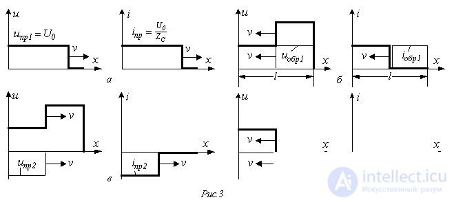
When the switch is closed (see Fig. 2), the voltage at the beginning of the line immediately reaches the value  , and
, and
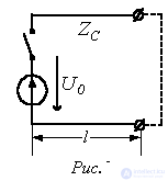
rectangular forward waves of voltage  and current
 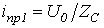 arise, propagating along the line at velocity V (see Fig. 3,a). At all points of the line that the wave has not yet reached, the voltage and current are zero. The point bounding the section of the line reached by the wave is called the wave front. In the case under consideration, at all points of the line passed by the wave front, the voltage equals
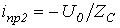
  , and the current -
  .
.
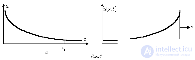
Note that under real conditions the wave shape, which depends on the internal resistance of the source, the line parameters, etc., always differs to a greater or lesser extent from a rectangular one.
Moreover, when a source with a different law of voltage variation is connected to the line, the wave shape will be different. For example, for an exponential variation of the source voltage (Fig. 4,a), the wave will have the shape shown in Fig. 4,b.
In the example under consideration with a rectangular voltage wave, during the first transit of the voltage and current waves (see Fig. 3,a), regardless of the load, they have the values  and
and  respectively, which is because the waves have not yet reached the end of the line, and, consequently, the conditions at the end of the line cannot affect the process.
At the instant  the voltage and current waves reach the end of the line of length l, and the discontinuity gives rise to backward (reflected) waves. Since the line is open-circuited at the end,
 ,
,
from which  and
and  .
.
As a result (see Fig. 3,b), the voltage in the part of the line reached by the wave front doubles, while the current drops to zero.
At the instant  , the backward voltage wave, which produces a line voltage of
  , reaches the source, which maintains a voltage of
  . As a result, a voltage wave
  arises together with a corresponding current wave
  (see Fig. 3,c).
At the instant  the voltage and current waves will approach the end of the line. Due to the open-circuit condition,
  and
and  (see Fig. 3,d). When these waves reach the beginning of the line, the voltage and current in it will become zero. Consequently, from this instant the transient process will repeat with a period of
  .
.
In the case of a line short-circuited at the end, during the time interval  the picture of the process corresponds to that considered above. For
  , since at the end of the line
  and
and  , which leads to an increase in the current in the line behind the wave front up to the value
  . For
. For  a voltage wave
  will travel from the source toward the end of the line, together with a corresponding current wave
 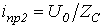 , producing a line current equal to
  , and so on. Thus, with each transit of the wave the current in the line increases by
  .
.
Note that in the real case, i.e. in the presence of power losses, the voltage in the line under open-circuit conditions will gradually approach the level determined by the source voltage, while the current under short-circuit conditions will be limited by the active resistance and conductance of the line, as well as by the internal resistance of the source.
References
Review Questions and Problems
Answer:  .
.
Answer:  .
.
 and a wave phase velocity of
 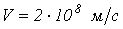 . At what frequencies will minima and maxima of the input impedance occur in it?
 ?
?
Comments