
Lecture
Unbalanced modes in the simplest characteristic cases (short circuit and open circuit) can be analyzed by constructing phasor diagrams.
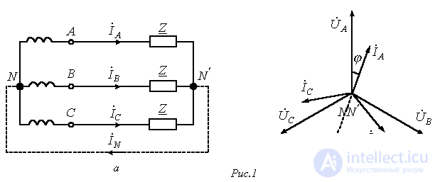
Let us consider the modes of an open phase and a short-circuited phase for a star connection in three-wire and four-wire systems. In doing so, we will compare them with the balanced operating mode of the circuit, whose phase voltages and currents will serve as the baseline. For this circuit (see Fig. 1,a), the phasor diagram of currents and voltages is shown in Fig. 1,b (it is assumed that the load  is of a resistive-inductive nature). Here

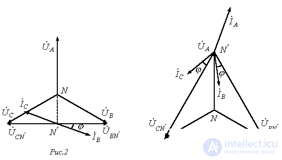
When phase A of the load is open, we arrive at the phasor diagram in Fig. 2.
In this case
 .
.
When phase A is short-circuited (three-wire system), the phasor diagram in Fig. 3 applies. From it follows: 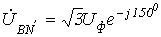 ;
; 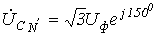 ;
; 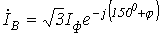 ;
; 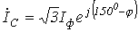 ;
; 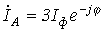 .
.
When phase A is open in a four-wire system (the neutral wire in Fig. 1,a is shown dashed, and the current phasor  is dashed in Fig. 1,b)
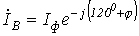 ;
; 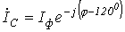 ;
; 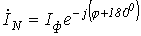 .
.
A balanced three-phase load connected in delta and the phasor diagram of voltages and currents corresponding to this case are shown in Fig. 4.
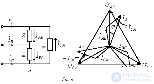
Here, with the same generator phase connection, 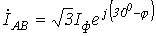 ;
; 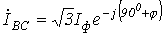 ;
; 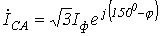 ;
; 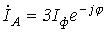 ;
; 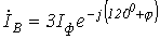 ;
; 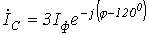 .
.
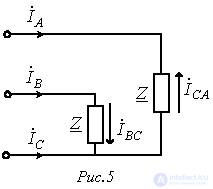
When the wire in phase A-B of the load is open, as can be seen from the circuit in Fig. 5,  ;
;  , while the currents themselves
  and
and  remain the same as in the circuit of Fig. 4,a, owing to the autonomy of phase operation for a delta-connected load. Thus,
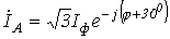 ;
; 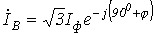 ;
; 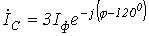 .
.
The circuit with an open line wire A-A' and the phasor diagram corresponding to this case are shown in Fig. 6.
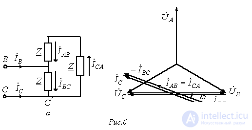
Here
 ;
; 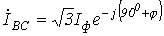 ;
;  .
.
Power in three-phase circuits
The instantaneous power of a three-phase energy source equals the sum of the instantaneous powers of its phases:
 .
.
The active power of the generator, defined as the average value of the instantaneous power over a period, equals
 .
.
Correspondingly, the active power of a three-phase load, taking into account losses in the neutral wire resistance,
 ,
,
the reactive power

and the apparent power
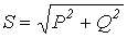 .
.
The total active power of a balanced three-phase system
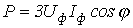 . . |
(1) |
Considering that in a balanced mode the following relations hold for a star connection

and for a delta connection –

on the basis of (1) we obtain, for both connection methods,
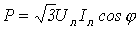 ,
,
where j is the phase-shift angle between the phase voltage and current.
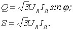
Similarly
Let us now prove the previously stated balance property of the two-phase Tesla system and of the balanced three-phase system.
1. The two-phase Tesla system
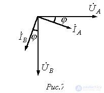
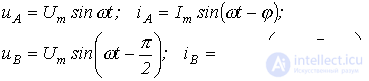
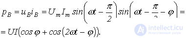
In accordance with Fig. 7
 |
(2) |
 . . |
(3) |
Taking (2) and (3) into account
 .
.
Thus, the total instantaneous power of the phases is a constant quantity, equal to the total active power of the source.
2. Balanced three-phase circuit
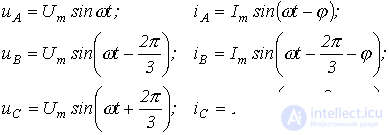
Then
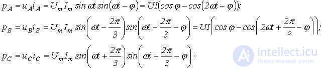
Hence
 ,
,
i.e., the balance property is thereby also proved for a balanced three-phase circuit.
Power measurement in three-phase circuits
Below are the practical schemes for connecting wattmeters to measure power in three-phase circuits.
1. Four-wire system, unbalanced mode.
The scheme shown in Fig. 8 is called the three-wattmeter scheme.
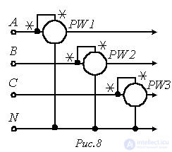
The total active power of the circuit is determined as the sum of the readings of the three wattmeters
 .
.
2. Four-wire system, balanced mode.
If the circuit's operating mode is balanced, then a single wattmeter (any one), connected according to the scheme in Fig. 8, is sufficient to determine the total active power. Then, for example, with the instrument connected in phase A,
 . . |
(4) |
3. Three-wire system, balanced mode.
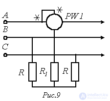
When there is no access to the neutral point, it is created artificially by connecting three additional resistors in a «star» scheme, as shown in Fig. 9 – the wattmeter scheme with an artificial neutral point. In this case, the condition  must be satisfied, where
  is the wattmeter winding's own resistance. Then the total active power of the three-phase system is determined according to (4).
4. Three-wire system, balanced mode; measurement of reactive power.
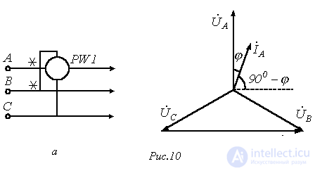
With a single wattmeter, in a balanced operating mode, the circuit's reactive power can be measured. In this case the wattmeter connection scheme takes the form shown in Fig. 10,a. According to the phasor diagram in Fig. 10,b, the power measured by the instrument is

Thus, the total reactive power

5. Three-wire system, unbalanced mode.
The scheme shown in Fig. 11 is called the two-wattmeter scheme. In it, the sum of the instrument readings equals the total active power of the circuit.
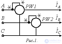
Indeed, the readings of the instruments in this scheme:
 .
.
Then

Finally, we note that if the circuit in Fig. 11 is operating in a balanced mode, then, based on the instrument readings, the total reactive power of the circuit can be determined
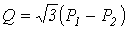 . . |
(5) |
References
Review Questions and Problems
Answer:  .
.
Answer: twice as much.
Answer:  .
.
Determine the wattmeter reading.
Answer: 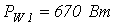 .
.
Determine the wattmeter readings.
Answer:  .
.
 is connected in a star. The line voltage is
  .
. .
.
Comments