
Lecture
In circuits with non-sinusoidal current, resonance conditions are possible for various harmonic components. As with sinusoidal currents, resonance at the k-th harmonic corresponds to an operating mode in which the k-th harmonics of voltage and current at the input of the circuit are in phase, in other words the input impedance (input admittance) of the circuit for the k-th harmonic is real.
Let there be a circuit as in Fig. 1,a, fed from a source of non-sinusoidal EMF, in which the capacitance of the capacitor can be smoothly varied from zero to infinity.
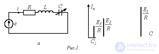
For the k-th harmonic of the current we can write
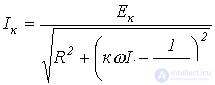 ,
,
where  - is the RMS value of the k-th harmonic of the EMF.
Thus, as C varies, the magnitude of the k-th harmonic of the current will change from zero at C=0 to  at
at  , reaching a maximum
  at resonance (see Fig. 1,b), determined by the capacitance value
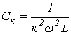 .
.
It should be noted that, although the amplitude of a harmonic EMF usually decreases as its order increases, at resonance for the k-th harmonic its value  can exceed the magnitude of the first harmonic of the current.
Resonance phenomena are used to extract harmonics of certain frequencies and suppress others. Suppose, for example, that in the circuit of Fig. 2 it is necessary to amplify the q-th harmonic of the current in the load and suppress the p-th.
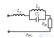
To suppress the p-th harmonic, the circuit  is tuned to a current-resonance condition:
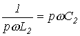 .
.
To extract the q-th harmonic, the whole circuit is tuned, for that harmonic, to a voltage-resonance condition:
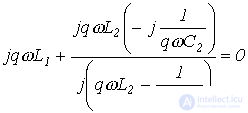 ,
,
from which, given known  and
and 
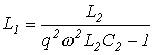 .
.
Note that the phenomena considered underlie the operation of L-C filters.
Features of the flow of non-sinusoidal currents
through passive circuit elements
1. Resistor.
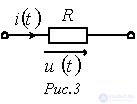
At 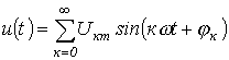 the current through the resistor (see Fig. 3)
 ,
,
where  .
.
Thus, on a resistive element, the non-sinusoidal voltage and current coincide in waveform and are similar to one another. In practice, this makes it possible to observe the current waveform on an oscilloscope by recording the voltage across a shunt.
2. Capacitor.
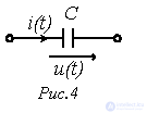
Let the voltage across the capacitor (Fig. 4) be described by the harmonic series 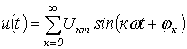 .
.
Distortion factor of the voltage waveform
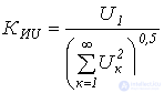 . . |
(1) |
Current through the capacitor
 .
.
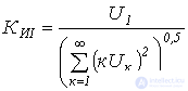
Then the distortion factor corresponding to the current waveform
 . . |
(2) |
Comparing (1) and (2) shows that  , i.e., the capacitor distorts the shape of the current waveform relative to the voltage, acting as a smoothing element for the latter.
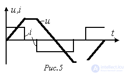
This is clearly illustrated in Fig. 5, in which the voltage waveform is closer to a sinusoid than the current waveform.
3. Inductor.
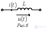
Taking into account the relationship between voltage and current for an inductor (Fig. 6)
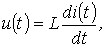
it can be shown in exactly the same way that, for an inductive element,  , i.e., the voltage waveform is distorted more than the current waveform. This case would correspond to Fig. 5 with the voltage and current curves interchanged. Thus, the inductor is a smoothing element for the current.
Given the above, in practice – for example in power semiconductor engineering – capacitor filters are used to smooth the rectified voltage, and chokes are used to smooth the current.
Higher harmonics in three-phase circuits
The voltages of three-phase energy sources are often substantially non-sinusoidal (strictly speaking, they are always non-sinusoidal to some degree). In this case, the voltages of phases B and C repeat the non-sinusoidal curve  of the voltage of phase A, shifted by one third of the period T of the fundamental harmonic:
 .
.
Let the k-th harmonic of the voltage of phase A be
 .
.
Then, taking into account that  , for the k-th harmonic voltages of phases B and C, respectively, we can write:
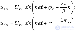
The whole set of harmonics k from 0 to  can be divided into three groups:
1.  - the harmonics of this group form symmetrical voltage systems whose sequence corresponds to the phase sequence of the fundamental harmonic, i.e. they form symmetrical positive-sequence voltage systems.
Indeed,

and
 .
.
2.  . For these harmonics the following relations hold:
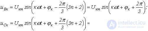
i.e. the harmonics of this group form symmetrical negative-sequence voltage systems.
3.  . For these harmonics the following holds
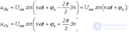
Thus, the voltage vectors of this group in all phases have, at every instant of time, the same magnitude and direction, i.e. these harmonics form zero-sequence systems.
Let us consider the features of three-phase system operation caused by the presence of harmonics that are multiples of three.
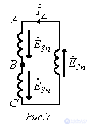
1. If the phases of the generator are connected in delta, then with non-sinusoidal phase EMFs the sum of the EMFs acting in the loop (see Fig. 7) is not equal to zero, but is determined by the harmonics that are multiples of three. These harmonics produce a current in the generator's closed delta even when its external circuit is open:
 ,
,
where  , and
, and  - is the impedance of the generator phase for the i-th harmonic that is a multiple of three.
2. If the phases of the generator are connected in open delta (see Fig. 8), then at terminals 1-2 there will be a voltage determined by the sum of the EMFs of the harmonics that are multiples of three:
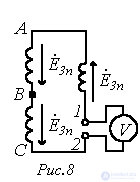
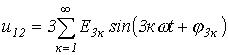
Thus, the voltmeter reading in the circuit of Fig. 8 is
 .
.
3. Regardless of the connection type – star or delta – the line voltages do not contain harmonics that are multiples of three.
For a star connection this is explained by the fact that, as noted, harmonics that are multiples of three form a zero sequence, and therefore disappear from the line voltages, which equal the difference of the phase voltages.
For a delta connection, the components of the phase EMFs that are multiples of three do not appear in the line (phase) voltages, since they are compensated by the voltage drops across the generator's own phase impedances.
Thus, for a delta connection the generator voltage is

and the current is
 .
.
For a star connection, in turn,
 .
.
4. Under a symmetrical load, the current in the neutral conductor is determined by the harmonics that are multiples of three, since they form a zero sequence:
 .
.
5. When connected in star with no neutral conductor, the load's phase currents do not contain harmonics that are multiples of three (in accordance with Kirchhoff's first law, the sum of the currents equals zero, which is impossible in the presence of these harmonics). Accordingly, these harmonics are also absent from the load's phase voltages, which are related to the currents by Ohm's law. Thus, when the generator's phase voltages contain harmonics that are multiples of three, the neutral displacement voltage in the symmetrical mode is determined by these harmonics
 .
.
References
Review Questions

Determine the RMS values of the line voltage, the phase voltages of the generator and the load, as well as the neutral displacement voltage.
Answer:  .
.
Determine the current in the neutral conductor if the load phase resistance R=10 Ohm.
Answer:  .
.
Determine the RMS value of the line current.
Answer:  .
.
 . The load resistance for the first harmonic

Comments