
Lecture
The equivalent generator method, based on the active one-port network theorem (also called the Thévenin–Helmholtz theorem), makes it possible to determine, quite simply, the current in a single branch of a complex linear circuit (the one of interest for the analysis) without finding the currents in the remaining branches. This method is especially effective when it is necessary to determine the current values in some branch for various values of resistance in that branch, while the resistances, as well as the EMFs and currents of the sources, remain constant in the rest of the circuit.
The active one-port network theorem is formulated as follows: if the active circuit to which a certain branch is connected is replaced by a source with an EMF equal to the voltage at the terminals of the open branch, and a resistance equal to the input resistance of the active circuit, the current in that branch will not change.
The course of the proof of the theorem is illustrated by the circuits in Fig. 1.
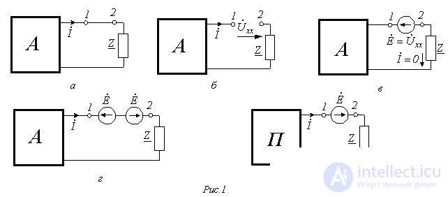
Suppose a certain branch with resistance Z is isolated in the circuit, and the rest of the circuit is denoted as an active one-port network A (Fig. 1,a). Let us open this branch between points 1 and 2 (Fig. 1,b). A voltage  appears at the terminals of this branch. If an EMF source
  with the direction shown in Fig. 1,c is now connected between terminals 1 and 2, then, as in the circuit of Fig. 1,b, the current in it will be zero. To make the circuit in Fig. 1,c equivalent to the circuit in Fig. 1,a, another EMF source
  must be inserted into the branch under consideration, compensating for the action of the first (Fig. 1,d). We will now find the current
  by the superposition principle, i.e. as the sum of two components, one of which is caused by the sources contained in the structure of the active one-port network, together with the EMF source
  located between terminals 1 and 2 on the left, and the other by the EMF source
  located between terminals 1 and 2 on the right. But the first of these components, according to Fig. 1,c, is equal to zero, and hence the current
  is determined by the second component, i.e. by the circuit in Fig. 1,e, in which the active one-port network A is replaced by a passive one-port network P. Thus, the theorem is proved.
The EMF and resistance indicated in the theorem can be interpreted as the corresponding parameters of a certain generator equivalent to the original active one-port network, from which the name of this method arose.
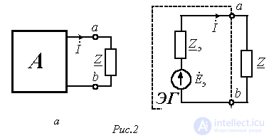
Thus, in accordance with this theorem, the circuit in Fig. 2,a, in which an active one-port network A of arbitrary structural complexity has been isolated with respect to the branch whose current is to be determined, can be transformed into the circuit in Fig. 2,b.
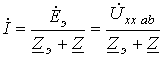
Hence the current  is found as:
 , , |
(1) |
where  - the voltage at the open terminals a-b.
Equation (1) is the analytical expression of the equivalent generator method.
The parameters of the equivalent generator (active one-port network) can be determined either experimentally or theoretically.
In the first case, in particular for direct current, the voltage  at the terminals of the active one-port network is measured with a voltmeter in the open-circuit mode, which is equal to
  . Then the terminals a and b of the active one-port network are short-circuited by means of an ammeter, which shows a current
  (see Fig. 2,b). Then, on the basis of the measurement results,
 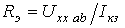 .
.
In principle, the parameters of the active one-port network are found similarly for sinusoidal current as well; only in this case it is necessary to determine the complex values of  and
and  .
.
When the parameters of the equivalent generator are determined theoretically, their calculation is carried out in two stages:
1. By any of the known methods for analyzing linear electric circuits, determine the voltage at terminals a-b of the active one-port network with the branch under investigation open.
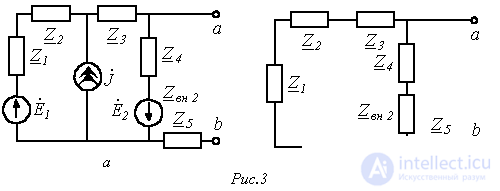
2. With the branch under investigation open, determine the input resistance of the active one-port network, which is thereby replaced by a passive one. This replacement is carried out by removing all energy sources from the structure of the active one-port network, while keeping their own (internal) resistances in their place. For ideal sources, this corresponds to short-circuiting all EMF sources and opening all branches containing current sources.
This is illustrated by the circuits in Fig. 3, where, to calculate the input (equivalent) resistance of the active one-port network in Fig. 3,a, the latter is transformed into a passive one-port network with the structure shown in Fig. 3,b. Then, according to the circuit in Fig. 3,b
 .
.
As an example of using the equivalent generator method for analysis, let us determine the dependence of the ammeter reading in the circuit of Fig. 4 as the resistance R of the variable resistor in the bridge diagonal changes within the range  . Circuit parameters: E=100 V; R1=R4=40 Ohm; R2=R3=60 Ohm.
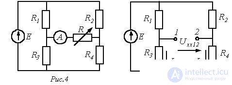
In accordance with the method described above for determining the parameters of the active one-port network, to find the value of  let us go to the circuit in Fig. 5, where the voltage
  at the open terminals 1 and 2 determines the required EMF
  . In this circuit
 .
.
To determine the input resistance of the active one-port network, let us transform it into the circuit of Fig. 6.
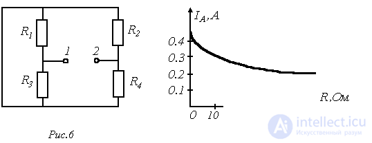
Viewed from terminals 1-2, the resistance of this passive one-port network is equal to:
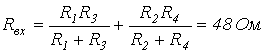 .
.
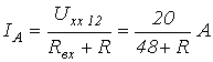
Thus, for the ammeter reading in the circuit of Fig. 4, in accordance with (1), we can write
 . . |
(2) |
Assigning values of R within its range of variation, on the basis of (2) we obtain the curve in Fig. 7.
As an example of using the equivalent generator method for analyzing a circuit under sinusoidal supply, let us determine at what value of load resistance  in the circuit of Fig. 8 the maximum power will be dissipated in it, and what that power will be equal to.
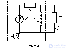
Circuit parameters:  ;
;  .
.
In accordance with the active one-port network theorem, the part of the circuit outlined by the dashed line in Fig. 8 is replaced by an equivalent generator with parameters
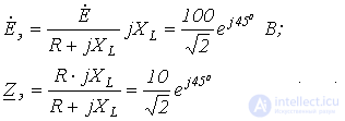
In accordance with (1), for the current  through
  we can write
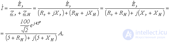
from which, for the magnitude of this current, we have
 (3)
(3)
Analysis of the resulting expression (3) shows that the current I, and hence the power, will be maximum if  ; from which
  , where the “-” sign indicates that the load
  is capacitive in nature.
Thus,
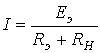 and
and 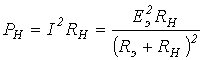 .
.
These relations are analogous to the corresponding expressions in a DC circuit, for which, as is known, the maximum power is dissipated in the load under the matched-load condition, the condition for which is  .
.
Thus, the required values are  and the maximum power:
  .
.
Variation theorem
The variation theorem is applied in cases where it is necessary to calculate how much the currents or voltages in the branches of a circuit will change if the resistance in one of the branches of that circuit changes.
Let us isolate in Fig. 9,a certain branches with currents  and
and  , while the rest of the circuit is denoted as an active four-terminal network A. We assume that the conductances
  and
and  are known.
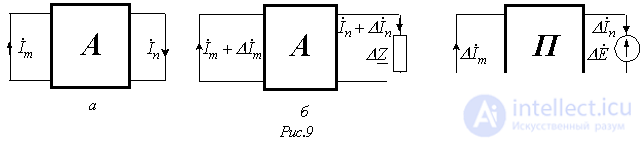
Suppose the resistance of the n-th branch changes by  . As a result, the currents in the branches of the circuit will become respectively equal to
  and
and  (Fig. 9,b). On the basis of the compensation principle, we replace
  by a source with EMF
  . Then, in accordance with the superposition principle, it can be considered that the increments of the currents
  and
and  are caused by
  in the circuit of Fig. 9,c, in which the active four-terminal network A is replaced by a passive one P.
For this circuit we can write

from which
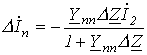 and
and 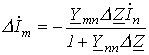 .
.
The relations obtained make it possible to determine the changes in the currents in the m-th and n-th branches caused by a change in the resistance in the n-th branch.
References
Review questions and problems
Answer:  .
.
Answer:  .
.
 obtained in the circuit of Fig. 8, using the equivalent generator method, determine the current in the branch with that resistance if the inductor in the structure of the active one-port network is replaced by a capacitor with resistance
  .
.
Comments