
Lecture
When asymmetry appears in an electrical network, the symmetry of the phase currents, phase and line voltages, voltage drops across the elements of the system, and other electromagnetic quantities is disturbed. It follows that in the case of an unsymmetrical short circuit and/or the appearance of series (longitudinal) asymmetry, one cannot limit the analysis to a single phase, as is done when studying a three-phase short circuit. If the conventional calculation method were used, it would be necessary to build an equivalent circuit for all three phases of the network under consideration, taking mutual inductance between them into account. The resulting system of equations would be extremely complex, so such a method of solving the problem is cumbersome even for a simple circuit.
Unsymmetrical short circuits and other unbalanced operating conditions can be calculated comparatively simply using the method of symmetrical components.
Any unbalanced system of three vectors can be decomposed into three symmetrical sets: positive-, negative-, and zero-sequence (Fig. 6.1).
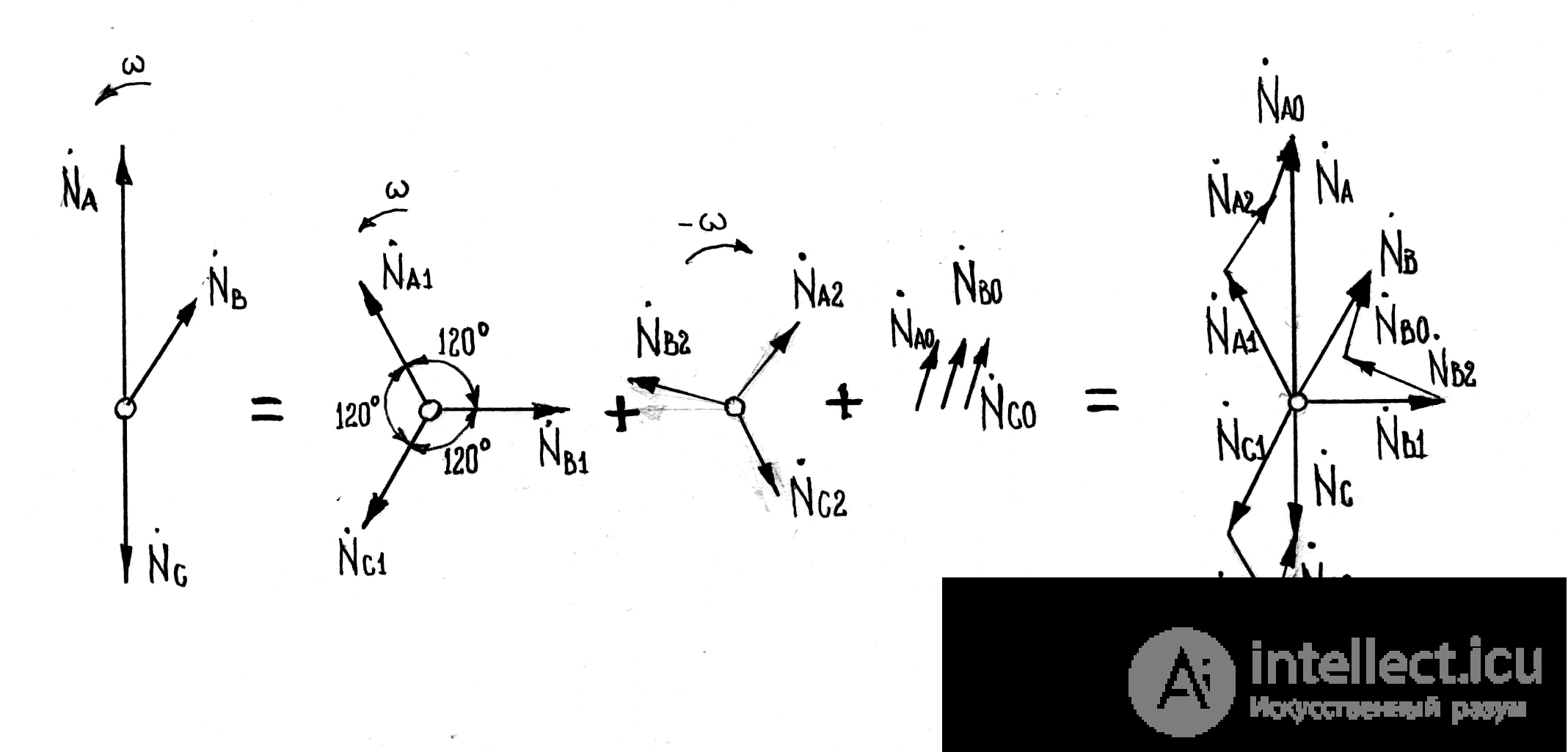
Fig. 6.1. Decomposition of an unbalanced three-phase system into symmetrical components
The positive-sequence system consists of three identical vectors, displaced from one another by 120o and following the same rotation order as the original system. The negative-sequence system likewise consists of three identical vectors, displaced from one another by 120o, but with a rotation order opposite to that of the original system. The zero-sequence system consists of three identical vectors that coincide in direction.
In a symmetrical three-phase system, each vector can be represented as:
NA = a NB = a2 N,
NB = a NC = a2 N, (6.1)
NC = a NA= a2 N ,
where a – rotation operator; a = e j120˚ = - 1/2 +j√3/2.
By definition, taking phase «A» as the special (reference) phase, we can write
NA = NA1 + NA2 + NA0,
NB = NB1 + NB2 + NA1 = a2 NA1 + a NA2 + NA0 , (6.2)
NC = NC1 + NC2 + NC 0 = a NA1 + a2 NA2 + NA0.
A rigorous mathematical analysis of unbalanced transient processes is significantly complicated by the fact that a pulsating rotor magnetic field, containing a full spectrum of higher harmonics, forms in synchronous machines under such conditions. The positive- and negative-sequence current systems of different frequencies then turn out to be mutually coupled. Therefore, in order to apply the method of symmetrical components, the following assumptions are made:
in symmetrical circuits, currents and voltages of different sequences do not interact with one another;
each circuit element presents its own specific impedance to currents of different sequences.
Consequently, the symmetrical components of the voltage drop across a given element are:
∆U1 = z1 I1,
∆U2 = z2 I2, (6.3)
∆U0 = z0I0,
where z1, z2, z0 – are respectively the positive-, negative-, and zero-sequence impedances.
The EMF of a symmetrical power source, such as a synchronous generator, forms the basic symmetrical system of vectors. During a symmetrical short circuit, such an EMF system produces only positive-sequence currents in the circuit.
When symmetry in the system is disturbed, unbalanced voltages arise, associated with the appearance of an unbalanced current system.
Negative- and zero-sequence currents produce corresponding magnetic fluxes in the generator, which, linking with its windings, in turn induce corresponding EMFs. These can be accounted for as a voltage drop across the generator's reactance for the given sequence, in the same way that the stator reaction EMF of the generator is accounted for as a voltage drop across the corresponding reactance.
In other words, it can be assumed that under any operating condition the generator produces only positive-sequence EMF, while the negative- and zero-sequence EMFs are zero. Thus, unbalanced conditions in the system can be calculated using equivalent single-line circuits for the positive-, negative-, and zero-sequence networks (Fig. 6.1), assuming that the currents flowing in the equivalent circuits of the different sequences depend only on the potential difference acting in the circuit and on the impedance of the corresponding sequence.
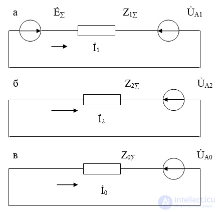
Fig. 6.2. Equivalent circuits for an unbalanced condition in an electrical circuit:
a – positive sequence, b – negative sequence, c – zero sequence
According to the diagrams (Fig. 6.2), the equation for each sequence has the form:
ỦA1 = Ẻ∑ - z1∑ Ỉ1,
ỦA2 = 0 - z2∑ Ỉ2, (6.4)
ỦA0 = 0 - z0∑ Ỉ0,
where ỦA1, ỦA2, ỦA0, Ỉ1, Ỉ2, Ỉ2 – symmetrical components of voltage and current at the short-circuit location (transverse asymmetry) or at the point of phase interruption (series asymmetry),
Ẻ∑ – resultant EMF;
z1∑, z2∑, z0∑ – resultant positive-, negative-, and zero-sequence impedances relative to the short-circuit point or the location of the phase interruption.

Comments