
Lecture
In accordance with the definition of this method, the calculation of a nonlinear circuit using it generally includes the following main stages:
1. The original characteristic of the nonlinear element is replaced by a broken line consisting of a finite number of straight-line segments.
2. For each segment of the broken line, the equivalent linear parameters of the nonlinear element are determined, and the corresponding linear equivalent circuits of the original circuit are drawn.
3. A linear problem is solved for each segment separately.
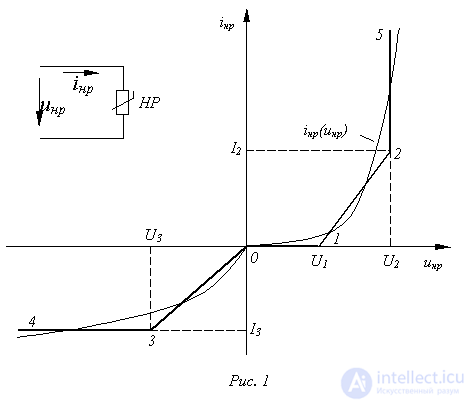
4. Based on the boundary conditions, the time intervals during which the representative point moves along each straight-line segment are determined (the limits of existence of the individual solutions).
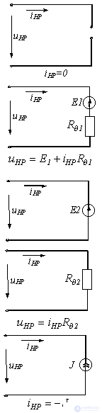
Suppose the volt-ampere characteristic (VAC) of a nonlinear resistor has the shape shown in Fig. 1. Replacing it with the broken line 4-3-0-1-2-5, we obtain the equivalent circuits for calculation, given in Table 1, and the corresponding linear relationships.
Calculating each of the resulting linear equivalent circuits, when the circuit contains one nonlinear element and an arbitrary number
of linear elements presents no difficulty. In this case, on the basis of the active two-terminal network theorem, the original nonlinear circuit is first reduced to a circuit containing an equivalent source with some linear internal resistance and a nonlinear element connected in series with it, after which it is calculated. When the circuit contains an alternating energy source, the operating (representative) point will continuously slide along the approximating characteristic, passing through the breakpoints. Passing through such points corresponds to an instantaneous change of the equivalent circuit. Therefore, the task of determining the required variable reduces not only to calculating the equivalent circuits, but also to determining the "switching" instants between them, i.e., finding the boundary conditions in time. The analysis becomes substantially more complicated if the circuit contains several nonlinear elements. The main difficulty in this case is that the combination of linear segments corresponding to the given input voltage (current) is not known in advance. The required combination of linear segments for all the nonlinear elements is found by trying out their possible combinations. For any assumed combination, the circuit parameters are known, and hence the voltages and currents for all the elements can be determined. If they lie within the limits of the corresponding linear segments, the assumed combination gives the correct result. If the variables of at least one nonlinear element go beyond the limits of the linear segment under consideration, another combination must be tried.
Table 1. Piecewise-linear approximation of the VAC of a nonlinear resistor
|
Curve segment |
Equivalent circuit |
Parameters of the elements |
Boundary conditions |
|||||
|
 |
 |
|
It should be noted that there is always a unique combination of linear segments of the characteristics of the nonlinear elements corresponding to a change of the input signal within certain limits.
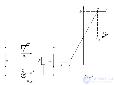
As an example, let us determine the voltage  in the circuit of Fig. 2, in which
 . The VAC of the nonlinear resistor is shown in Fig. 3, where
  .
.
Solution
1. In accordance with the given VAC, on segment 1-2 the nonlinear resistor is replaced by a linear resistor with resistance
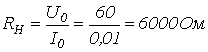 ,
,
on segment 2-3 by a current source with current  , and on segment 4-1 by a current source with current
  .
.
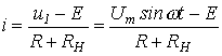
2. On the basis of this equivalent replacement, for the current on segment 1-2 of the VAC we can write:
 |
(1) |
from which

When the representative point moves along segment 2-3 of the VAC, we have
 ,
,
when moving along segment 1-4 of the VAC -
 .
.
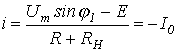
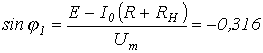
3. We determine the time intervals of motion of the representative point along the individual segments of the VAC. For breakpoint 1, based on (1), the following equation holds
or
 .
.
From this we obtain two values of the instantaneous phase of the supply voltage within one period, corresponding to point 1:  . The first value determines the transition of the representative point from segment 4-1 to segment 1-2, the second – from segment 2-1 to segment 1-4.
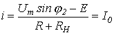
Similarly, we write for breakpoint 2 of the VAC
or
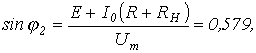
from which  (the value corresponding to the transition from segment 1-2 to segment 2-3) and
  (the value corresponding to the transition from segment 3-2 to segment 2-1).
Thus, for one period of the supply voltage we obtain
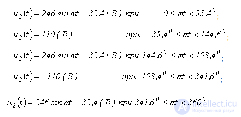
In accordance with the periodicity of the sinusoidal function, these solutions repeat every 360°n.
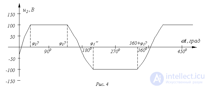
Fig. 4 shows the graph of the relationship for the required quantity.
Using an analytical expression to approximate the characteristic of a nonlinear element makes it possible to carry out the calculation with the least effort when the time-dependence of one of the variables governing the operation of the nonlinear element (current or voltage for a resistor, flux linkage or current for an inductor, charge or voltage for a capacitor) is given, or follows from a preliminary analysis of the physical conditions of the process, as was the case in solving the previous problems in this section. If such certainty is absent, the problem can in general be solved only approximately. One of these methods, the most widely used in practice, is the harmonic balance method.
The method is based on expanding periodic functions in a Fourier series. In general, the required variables in a nonlinear electrical circuit are non-sinusoidal and contain an infinite spectrum of harmonics. The expected solution can be represented as the sum of the fundamental and several higher harmonics, whose amplitudes and initial phases are unknown. Substituting this sum into the nonlinear differential equation written for the required quantity, and equating, in the resulting expression, the coefficients of the harmonics (sine and cosine functions) of equal frequencies on its left- and right-hand sides, we arrive at a system of 2n algebraic equations, where n is the number of harmonics taken into account. It should be noted that an exact solution requires taking into account an infinite number of harmonics, which is practically impossible. As a result of limiting the number of harmonics considered, the exact balance is violated, and the solution becomes approximate.
The procedure for calculating a nonlinear circuit by this method generally includes the following main stages:
 and initial phases
  that are unknown at this stage.
 and initial phases
  of the expansion of the quantity being determined.
 and
and  .
.A special case of the harmonic balance method is the first-harmonic calculation method for non-sinusoidal quantities (the harmonic linearization method), in which the higher harmonics of the required variables, as well as of the input actions, are neglected. The analysis uses the characteristic of the nonlinear element for the first harmonics, obtained by substituting the first harmonic of one of the two variables defining this characteristic into the analytical expression of the nonlinear characteristic for instantaneous values, and finding the nonlinear relationship between the amplitudes of the first harmonics of these variables. The calculation stages correspond to those set out for the harmonic balance method. Since the resulting system of nonlinear equations is of the second order, in a number of cases it becomes possible to solve it analytically. Furthermore, since only the first harmonics of non-sinusoidal quantities are considered, the phasor method can be used in the calculation.
Suppose, for example, that in a circuit fed from a sinusoidal voltage source  and consisting of a linear resistor
  connected in series with a nonlinear coil, whose weber-ampere characteristic is given by an approximation of the form
  , it is required to determine the first harmonic of the current, given by the expression
  , where
  and
and  are unknown (the quantities sought).
To solve the problem, we determine the analytical expression for the characteristic  for the first harmonics:

from which
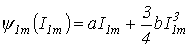 . . |
(2) |
After substituting the current expression and relation (2) into the circuit's state equation

we obtain

or

From the last equation we obtain a system of equations
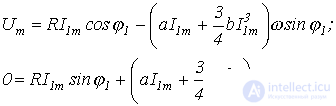
from which we find the required parameters  and
and  .
.
 and a nonlinear coil, whose weber-ampere characteristic is approximated by the expression
  , where
  , are connected in series and supplied from a sinusoidal voltage source
  . Restricting consideration to the first and third harmonics, determine the flux linkage.
Answer:  .
.
Answer:  .
.


Comments