
Lecture
Electric circuits may contain elements that are inductively coupled to one another. Such elements can link circuits that are electrically (galvanically) isolated from each other.
When a change in current in one of the circuit elements causes an EMF to appear in another circuit element, these two elements are said to be inductively coupled, and the resulting EMF is called the mutual-inductance EMF. The degree of inductive coupling between elements is characterized by the coupling coefficient
 , , |
(1) |
where M is the mutual inductance of the circuit elements (dimension - H);  and
and  are the self-inductances of these elements.
It should be noted that always k<1.
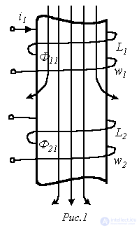
Suppose we have two coaxial coils, in the general case with a ferromagnetic core (see Fig. 1). Fig. 1 schematically shows the magnetic field pattern in the presence of current i1 in the first coil (the direction of the magnetic-flux field lines is determined by the right-hand screw rule). The turns of the first coil are linked with the self-induction magnetic flux F11, while the turns of the second coil are linked with the mutual-induction magnetic flux F21, which differs from F11 (F21< F11) due to leakage fluxes.
By definition
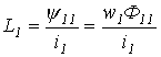 ; ; |
(2) |
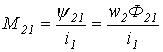 . . |
(3) |
If, conversely, we now pass current i2 through the second coil, then correspondingly we obtain
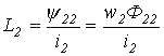 ; ; |
(4) |
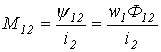 . . |
(5) |
In this case
 . . |
(6) |
It should be noted that the coupling coefficient could equal 1 only if  and
and  , that is, when the entire flux produced by one coil completely linked the turns of the other coil. In practice, even different turns of the same coil are linked by different fluxes. Therefore, taking leakage into account,
  and
and  . In this connection
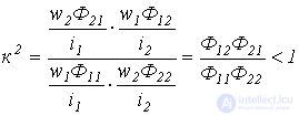 .
.
Let us consider the AC circuit in Fig. 2, in which two inductors  and
and  , inductively coupled to each other, and a resistor R are connected in series.
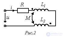
When the current i in the circuit changes, self- and mutual-induction EMFs are induced in the coils. In this case, by Lenz's law, the mutual-induction EMF must have a direction such that it opposes the change in the mutual-induction flux.
Then, if a harmonically varying current  flows in the circuit, an EMF is induced in the first coil
 , , |
(7) |
and in the second -
 . . |
(8) |
The coils can be connected so that the self-induction EMF adds to the mutual-induction EMF; if one of the coils is reconnected, the mutual-induction EMF will be subtracted from the self-induction EMF. One of the terminals of each coil is marked on the diagram, for example with a dot or an asterisk. This mark means that, for example, when the current in the first coil, flowing from the dot, increases, a mutual-induction EMF is induced in the second coil acting from the other end toward the dot. A distinction is made between cumulative (aiding) and differential (opposing) connections of the coils. In a cumulative connection, the currents in the coils are identically oriented with respect to their like-marked terminals. In this case the self- and mutual-induction EMFs add up - the case shown in Fig. 2. In a differential connection of the coils, the currents are oriented differently with respect to the like-marked terminals. In this case the self- and mutual-induction EMFs are subtracted. Thus, the type of coil connection (cumulative or differential) is determined jointly by the way the coils are wound and the direction of the currents in them.
Switching to the complex form of (7) and (8), we obtain
 ; ; |
(9) |
 , , |
(10) |
where  - is the mutual-induction reactance (Ohm).
To determine the current in the circuit of Fig. 2, we write
 ,
,
from which
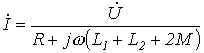 .
.
Air-core (linear) transformer
One of the most important elements of electric circuits is the transformer, which serves to convert the values of currents and voltages. In the simplest case, a transformer consists of two galvanically unconnected and stationary coils without a ferromagnetic core. Such a transformer is called an air-core transformer. It is linear. The presence of a ferromagnetic core would give the transformer nonlinear properties.
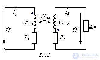
Fig. 3 shows the equivalent circuit of a transformer whose primary winding is connected to voltage U1, while a load with resistance  is supplied from the secondary winding.
In a transformer, energy is transferred from the primary circuit to the secondary circuit by means of the magnetic field. If, under the action of the source voltage, an alternating current arises in the primary circuit, then, owing to the magnetic coupling of the coils, an EMF is induced in the secondary circuit, causing current to flow in the load.
By Kirchhoff's second law, for the primary and secondary circuits of the transformer we can write
 ;
;
 .
.
Thus, the equations of the air-core transformer have the form:
 ; ; |
(11) |
 ,. ,. |
(12) |
where  and
and  are the active (resistive) resistances of the windings;
  .
.
If equations (11) and (12) are solved for  , first substituting
  into (12) and denoting
  ;
;  , we obtain
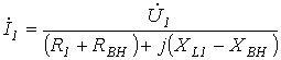 , , |
(13) |
where  ;
;  are the reflected active and reactive resistances.
Thus, according to (13), the air-core transformer, viewed from the primary winding side, can be regarded as a two-terminal network with impedance  .
.
Power balance in circuits with inductively coupled elements
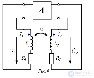
Suppose we have the circuit of Fig. 4, where A is some active four-terminal network. For this circuit we can write
 ;
;
 .
.
Let us denote the currents  and
and  as:
as:  ;
;  .
.
Then for the complex apparent powers of the first and second branches, respectively, we can write:
 ;
;
 .
.
Let us consider in these equations the terms involving the mutual inductance:
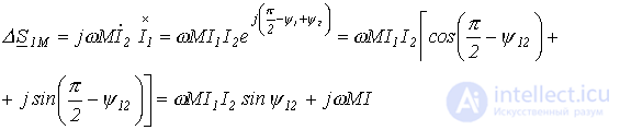 |
(14) |
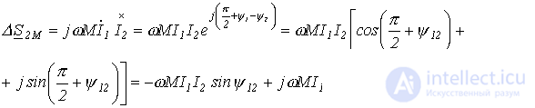 . . |
(15) |
where  .
.
From (14) and (15) it follows that
 ; ; |
(16) |
 . . |
(17) |
Relation (16) shows that active power is transferred from the first coil to the second. In this case, the total reactive power due to the mutual induction is equal to zero, since  . This means that inductively coupled elements do not affect the overall active-power balance of the circuit.
The total reactive power due to mutual induction is equal to
 .
.
Thus, the general power-balance equation, taking inductively coupled elements into account, has the form
 , , |
(18) |
where the “+” sign is used for a cumulative (aiding) connection of the coils, and “-” for a differential (opposing) one.
The calculation of branched circuits in the presence of mutual inductance can be carried out by writing equations using Kirchhoff's laws or by the mesh-current method. Direct application of the node-potential method for calculating such circuits is unacceptable, since in this case the current in a branch also depends on the currents of other branches, which induce mutual-induction EMFs.
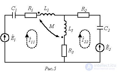
As an example of the calculation of circuits with inductively coupled elements, let us write the mesh equations for the circuit in Fig. 5:

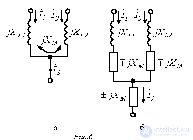
To get around the above-mentioned restriction on the use of the node-potential method for calculating the circuits under consideration, equivalent transformations can be used, illustrated by the circuits in Fig. 6, where the circuit in Fig. 6,b is equivalent to the circuit in Fig. 6,a. Here the upper signs are used for a cumulative (aiding) connection of the coils, and the lower signs for a differential (opposing) one.
 ;
;  ;
;  ;
;  ;
;  ;
;  .
.Answer:  .
.

Comments