
Lecture
A transverse asymmetry at an arbitrary point of a three-phase system can, in general form, be represented by connecting three unequal impedances at that point. This approach makes it possible to obtain a solution in general form, from which the solutions for all particular cases then follow. However, this approach leads to cumbersome expressions, so it is considered much simpler and more illustrative to carry out the solution for each particular case using its characteristic boundary conditions.
This section examines the three principal types of unsymmetrical short circuits (two-phase, single-phase-to-ground, and two-phase-to-ground), which occur most often in systems with a grounded neutral. In the derivations given below it is assumed that only the fundamental harmonics of current and voltage are being considered, that the individual-sequence circuits consist only of reactances, and that the resulting EMF 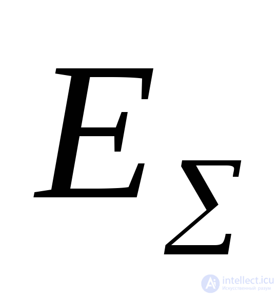 and the resulting reactances
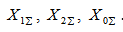 have been found.
In writing the boundary conditions we shall assume that phase «A» is in conditions different from those of the other two phases, i.e., it is, as they say, the special phase. The positive direction of currents will be taken as the direction toward the point of short circuit.
To simplify the notation, the index denoting the type of short circuit is retained only when writing the boundary conditions and in the final results.
Taking phase «A» as the special phase, the equations for the EMFs and voltages of the loop can be written for the corresponding sequences:
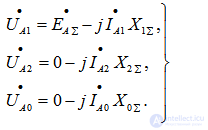 (7.1)
(7.1)
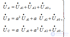
The phase currents and voltages at the point of short circuit can be found from the formulas obtained on the basis of (6.2)
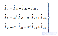 (7.2)
(7.2)
 (7.3)
(7.3)
In the nine equations (7.1–7.3) there are 12 unknowns ( ). To solve this system of equations, three more equations must be written, arising from the boundary conditions of the corresponding type of unsymmetrical short circuit.
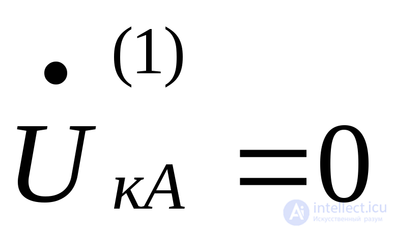
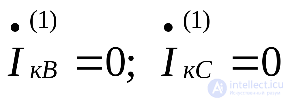
For a short circuit of phase «A» to ground (Fig. 7.1), the boundary conditions are:
 (7.4)
(7.4)
 (7.5)
(7.5)
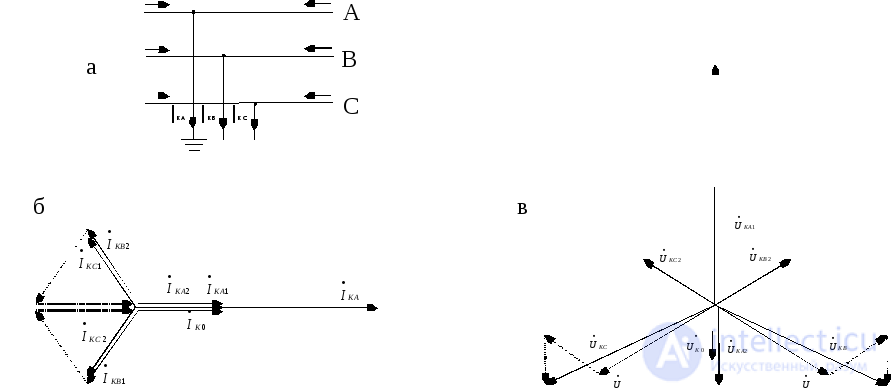
Fig. 7.1. Single-phase short circuit: a – schematic diagram, b – vector diagram of the voltages at the point of short circuit, c – the same for currents
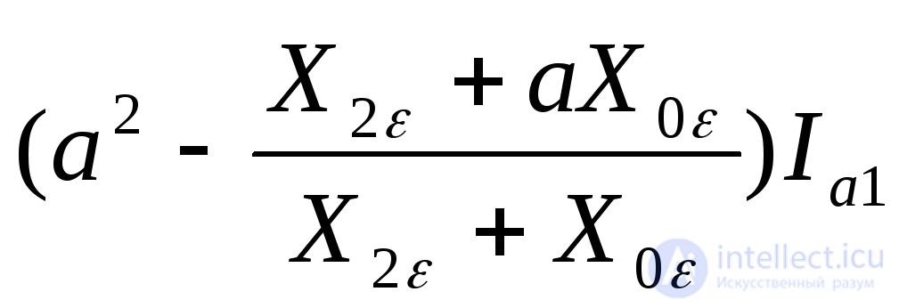
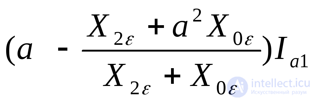
Subtracting the third equation from the second (7.2), taking (7.5) into account, we obtain
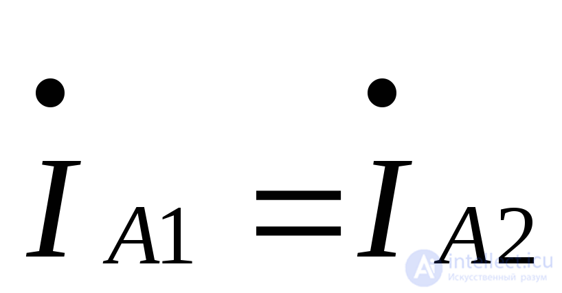 . (7.6)
Adding the third and second equations of (7.2), taking (7.5) and (7.6) into account, we have
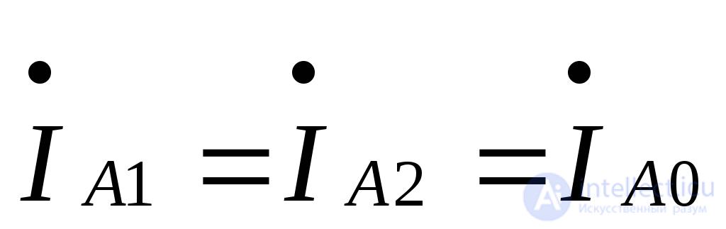 .
. (7.7)
(7.7)
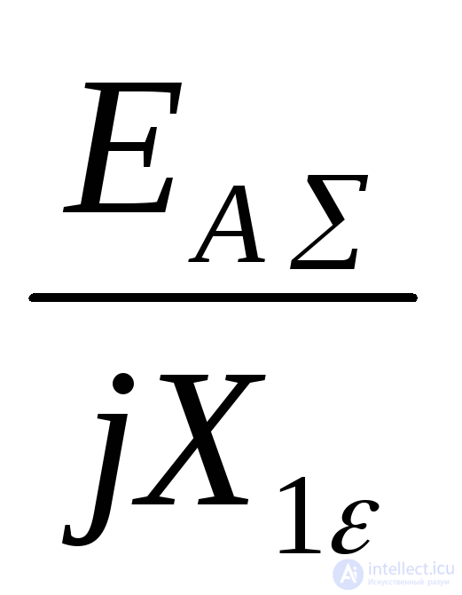
Taking equality (7.7) and condition (7.4) into account, from the sum of equations (7.1) we can write the formula for determining the positive-sequence current of phase «A»:
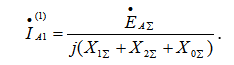 . (7.8)
The current in the faulted phase
 . (7.9)
The ratio of the current in the faulted phase to the positive-sequence current is called the current interconnection coefficient. For a single-phase short circuit to ground
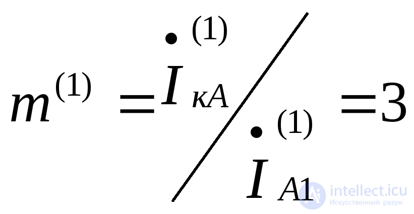 . (7.10)
At the initial instant of the short circuit, the current in the phase is
 , (7.11)
where 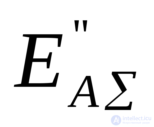 is the subtransient interphase resulting EMF.
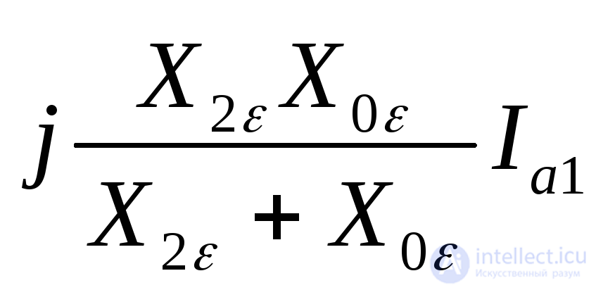
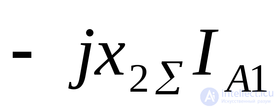
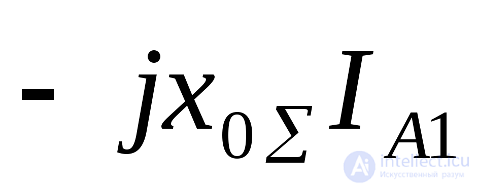
The voltages of the symmetrical components, on the basis of the system of equations (7.1), for the zero and negative sequences, taking (7.7) into account:
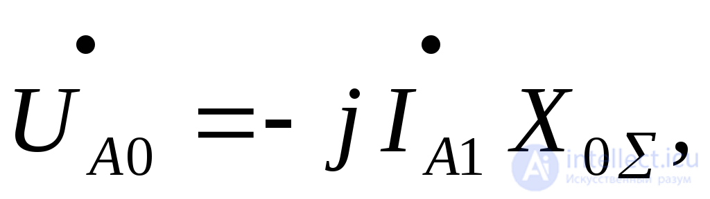 (7.12)
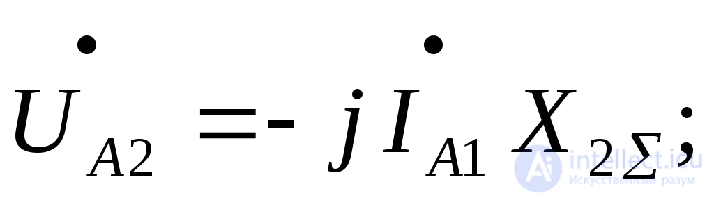 (7.13)
of the positive sequence, taking into account (7.4.), (7.1.), (7.13.):
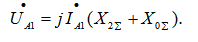 (7.14)
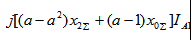
Phase (with respect to ground) voltages at the point of short circuit:
 , (7.15)
 . (7.16)
Fig. 7.1,b shows the vector diagrams of the voltages and currents at the point of short circuit. The angle between the vectors of the sound phases depends on the ratio between 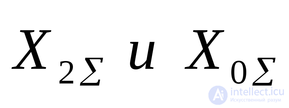 . It varies within wide limits:
 . At
. At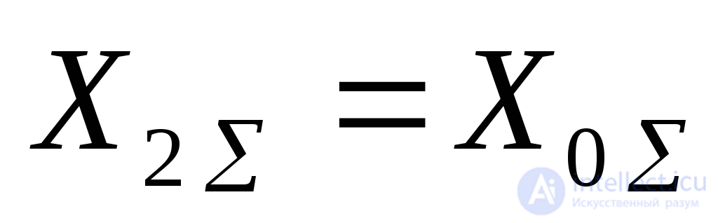 the angle
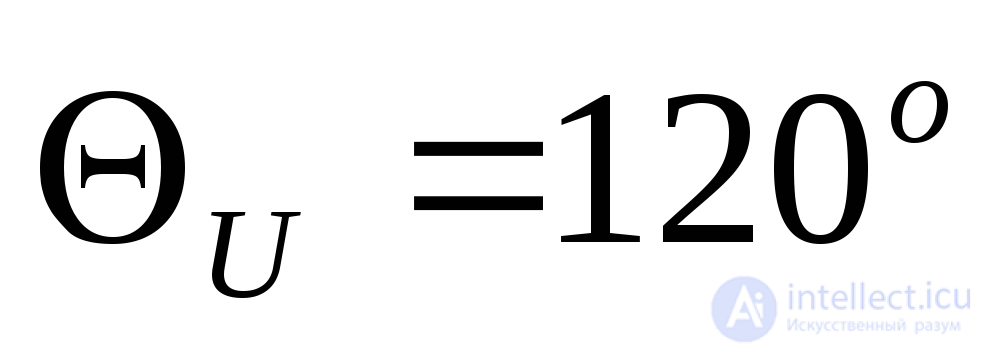 .
.
The boundary conditions for a fault between phases «B» and «C» have the form
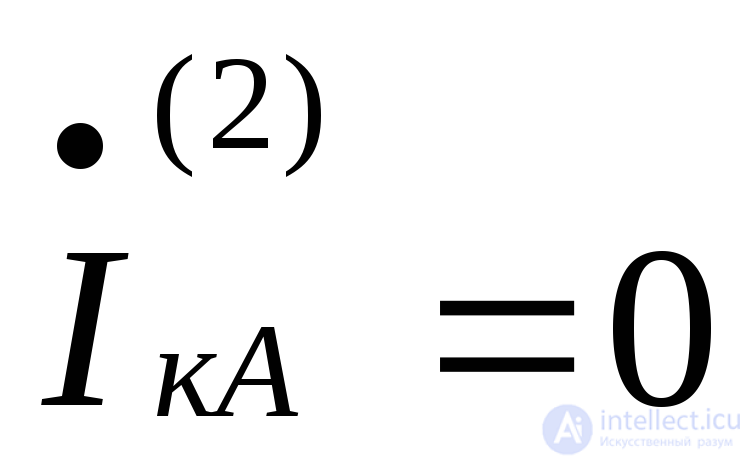 , (7.17)
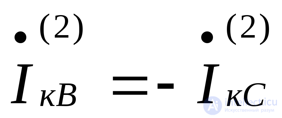 , (7.18)
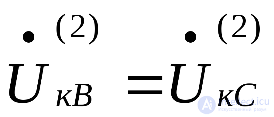 . (7.19)
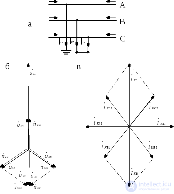
Fig. 7.2. Two-phase short circuit: a – schematic diagram, b – vector diagram of the voltages at the point of short circuit, c – the same for currents
Since the sum of the phase currents equals zero, the system is balanced, and consequently 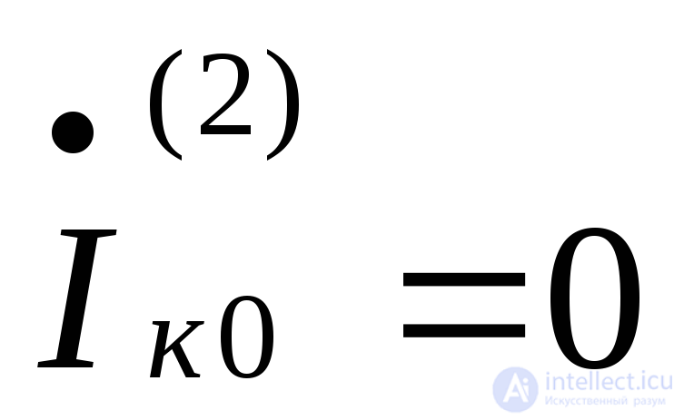 . In this case, according to (7.2), the current of phase «A» will be
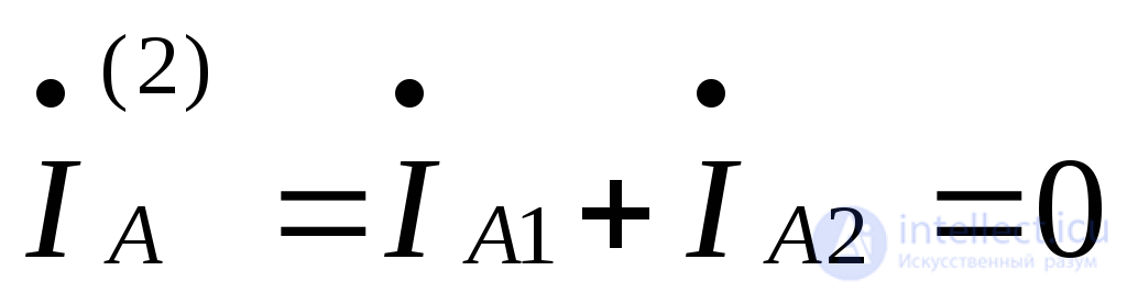 , from which
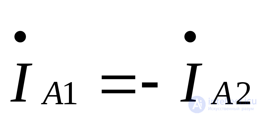 . (7.20)
From condition (7.19) and (7.3)
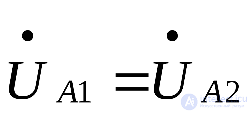 . (7.21)
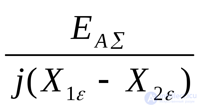
Substituting the values 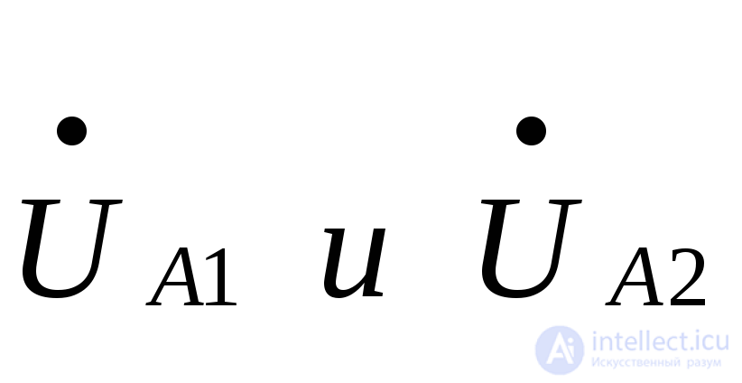 , from (7.1) and (7.21) we obtain the expression for determining the positive-sequence current in a two-phase short circuit
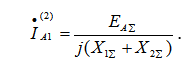 . (7.22)
+Next, carrying out calculations analogous to those in the preceding section (7.2.), we determine the phase currents and voltage, as well as the current interconnection coefficient, for a two-phase short circuit. The results obtained are summarized in Table 7.1.
A two-phase short circuit to ground is characterized by the boundary conditions
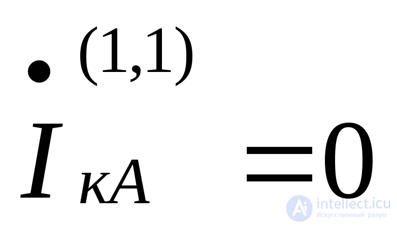 , (7.23)
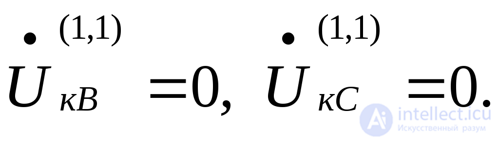 (7.24)
Taking (7.23) into account, we obtain 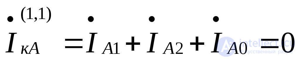 , from which the positive-sequence current is
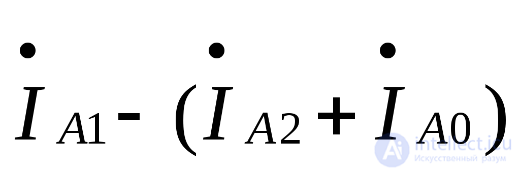 . (7.25)
From conditions (7.24) and using (7.3), we have
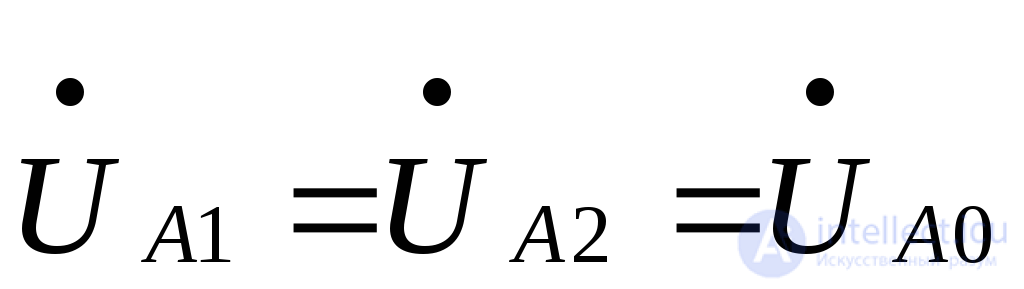 . (7.26)
Using the last equality and equations (7.1), we obtain
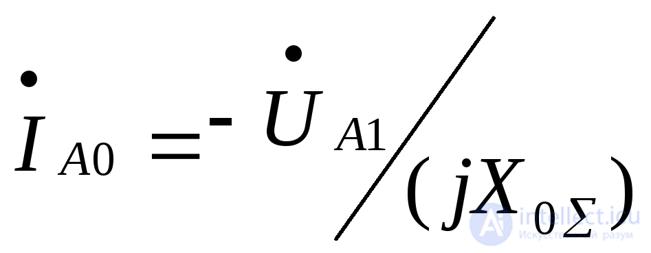 , (7.27)

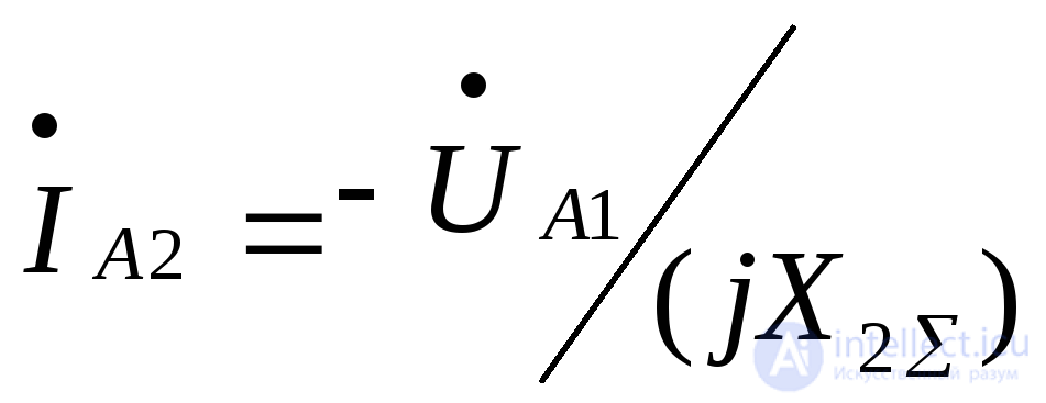 . (7.28)
Taking (7.27), (7.28) into account, from (7.25) we have
 . (7.29)
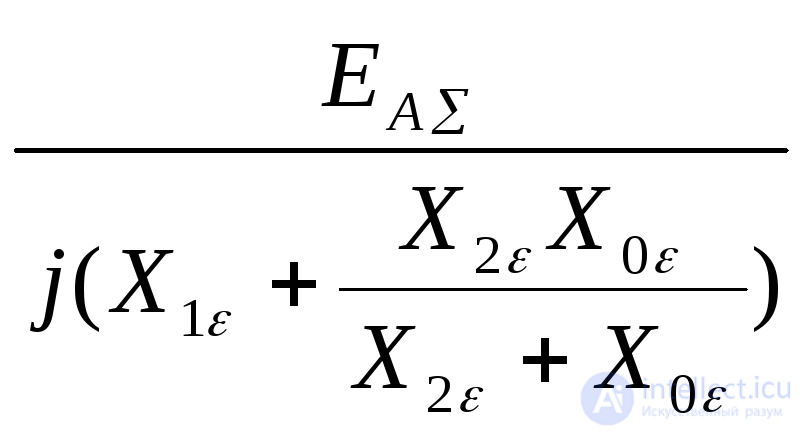
Equating the value 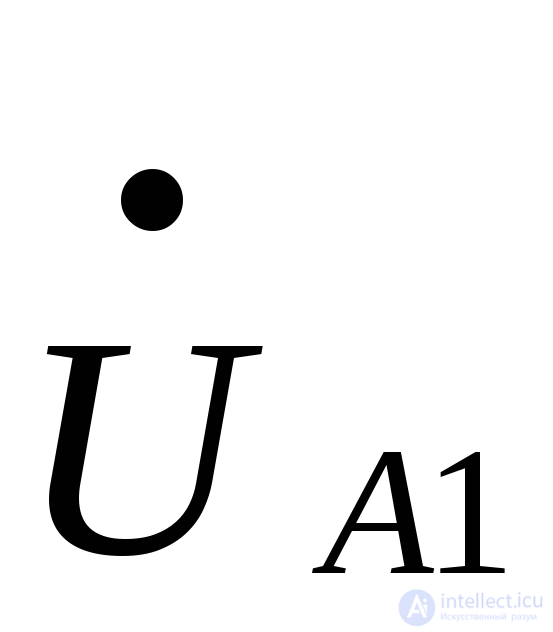 from (7.1) and (7.29), we can write
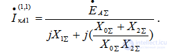 . (7.30)
Next, proceeding analogously to Section 7.2, equations can be obtained for calculating the phase currents and voltages, the current interconnection coefficient, and the ground current. The results obtained are given in Table 7.1.
The vector diagrams of the voltages and currents at the point of a two-phase short circuit to ground are shown in Fig. 7.3,b,c. The angle 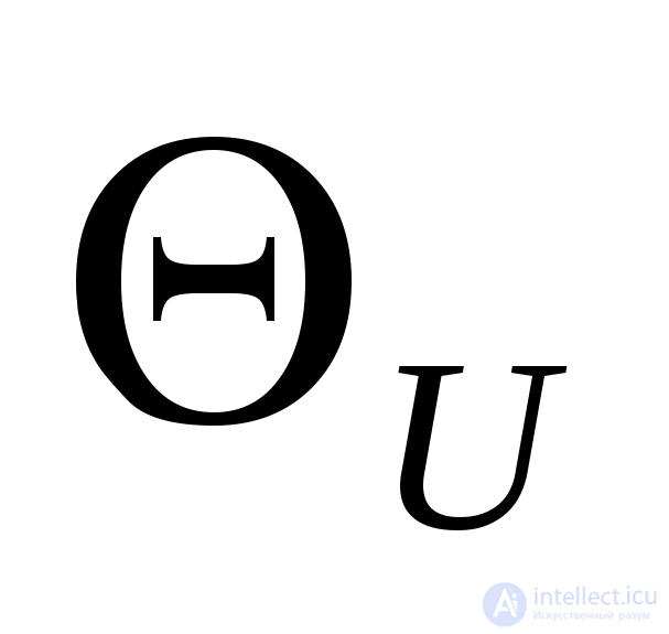 between the currents of the faulted phases can vary within the range
 , tending toward the lower limit at
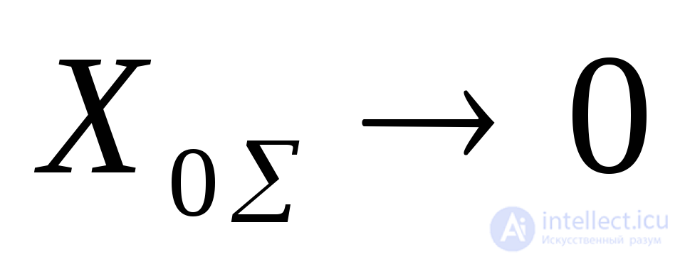 and toward the upper limit at
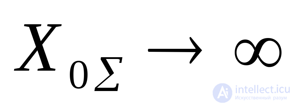 , which corresponds to the conditions of a two-phase short circuit without a connection to ground.
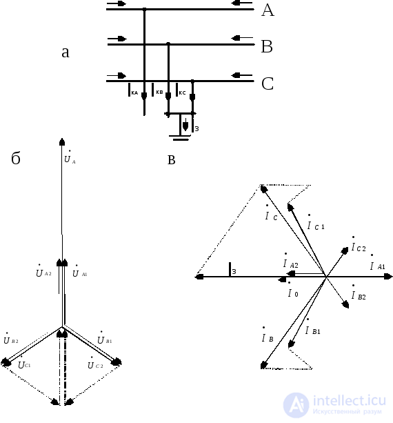
Fig. 7.3. Two-phase short circuit to ground: a – schematic diagram, b – vector diagram at the point of short circuit, c – the same for currents
In short circuits, the transition resistance is mainly determined by the resistance of the electric arc, which to a first approximation can be regarded as a pure resistance 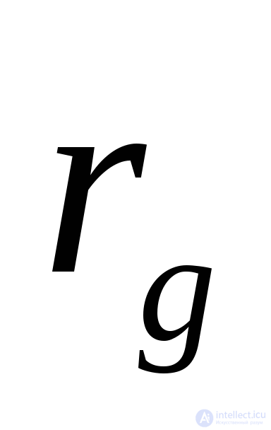 .
.
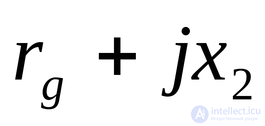
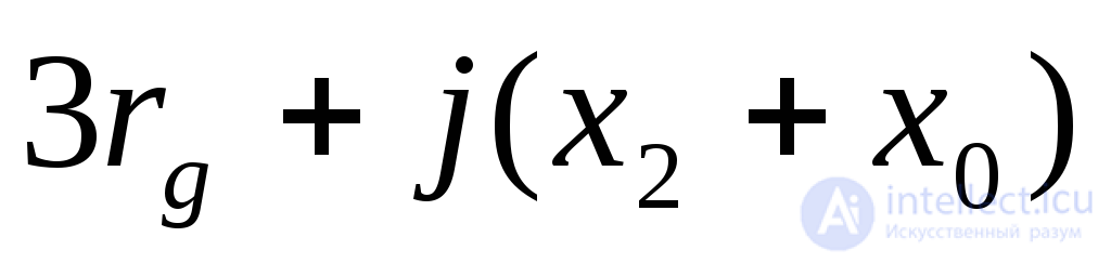
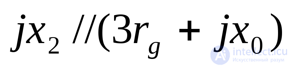
Fig. 7.4 shows the diagrams of unsymmetrical short circuits taking the arc resistance into account. Here a two-phase short circuit through an arc is represented as a solid short circuit at a branch whose phases have equal resistance 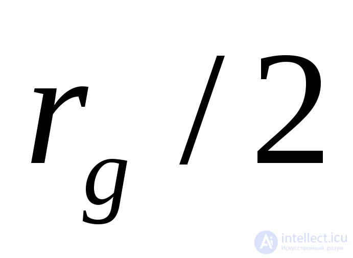 . Into the single-phase short-circuit network, equal resistances
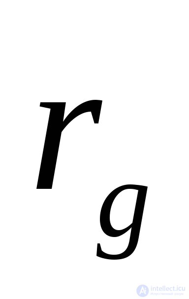 are introduced into each phase. Such artificial techniques do not violate the boundary conditions and make it possible, in the simplest way, to obtain the design formulas for the sequence currents and voltages and for the actual phase currents and voltages, by analogy with the formulas (Table 7.1).
For a single-phase short circuit through an arc, the formula for determining the positive-sequence current has the form
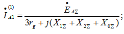 (7.31)
for a two-phase short circuit:
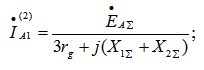 (7.32)
for a two-phase short circuit to ground:
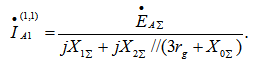 (7.33)
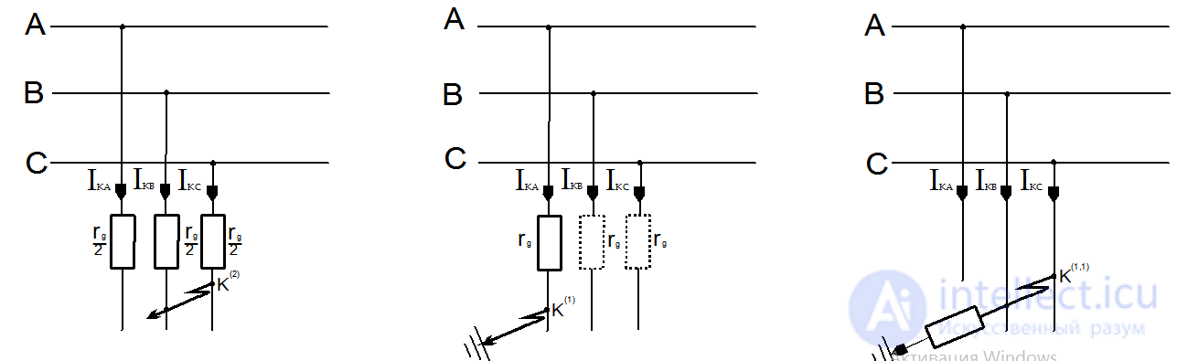
Fig. 7.4. Diagrams of unsymmetrical short circuits through an arc for two-phase (a), single-phase (b), and two-phase-to-ground (c) faults
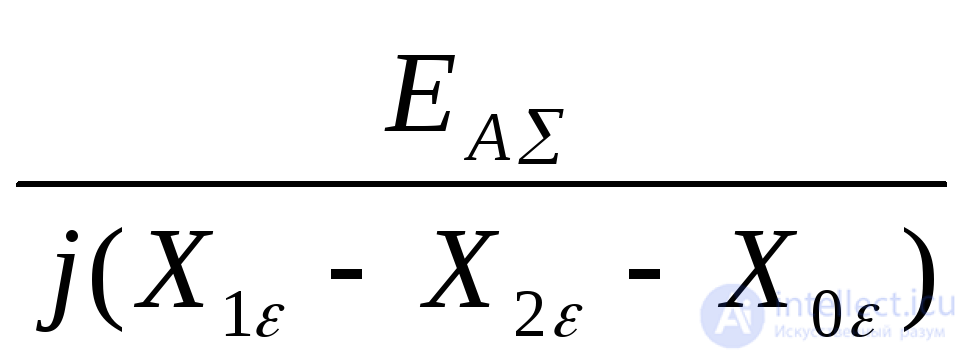
The structure of expressions (7.8), (7.22) and (7.30) makes it possible to write, in general form, the positive-sequence current of phase «A» for any type of unsymmetrical short circuit through the circuit parameters:
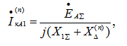 (7.34)
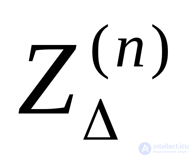
where (n) denotes the type of short circuit; 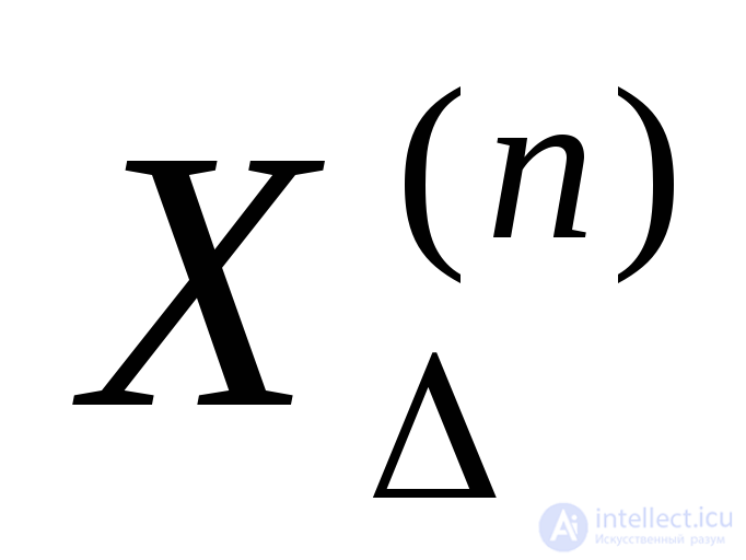 is the additional resistance depending on the type of short circuit (Table 7.1).
Taking into account that the phase currents at the point of short circuit are proportional to the positive-sequence current, the modulus of the phase current at the point of an unsymmetrical short circuit is determined by the expression
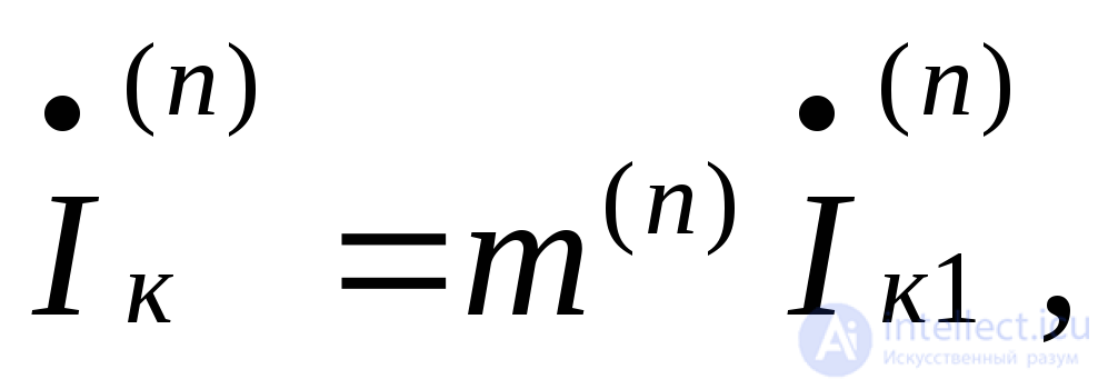 (7.35)
where m(n) – from the data of Table 7.1.
The generalized form of expression (7.35) allowed N. N. Shchedrin to formulate the following highly important statement.
The positive-sequence current of any unsymmetrical short circuit can be determined as the current for a three-phase short circuit at a point removed from the actual point of short circuit by an additional resistance 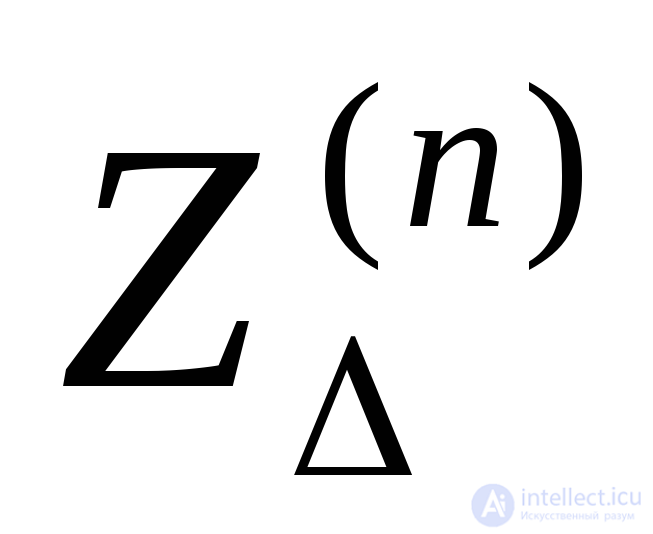 , which does not depend on the parameters of the positive-sequence circuit and, for each type of short circuit, is determined by the resulting negative- and zero-sequence impedances with respect to the point of the circuit under consideration, and also, in the general case, by the resistance of the arc that has arisen.
This statement, known as the rule of positive-sequence equivalence, is valid on the condition that only the fundamental harmonic of the unsymmetrical short-circuit current is considered.
The established identity between the positive-sequence currents of an unsymmetrical short circuit and the currents of some equivalent three-phase short circuit confirms that all previously obtained expressions for three-phase short-circuit current can be extended to the case of unsymmetrical short circuits.
The rule of positive-sequence equivalence and the established values of xΔ(n) m(n) (see Table 7.1) make it possible to compare the various types of short circuit quite simply. We shall confine this comparison to the conditions under which the short-circuited circuit is purely inductive.
Assuming that short circuits of various types occur in turn at the same point of the system and under the same initial conditions, on the basis of the data in Table 7.1 the following inequalities can be written:



Let us find out the limits within which the values of the currents in unsymmetrical short circuits can lie compared with the values of the current of a three-phase short circuit occurring at the same point of the system. Knowledge of these limits is of practical interest, since it makes it possible, from the known value of the three-phase short-circuit current, to estimate, to a first approximation, the possible largest and smallest values of current for unsymmetrical short circuits.
For example, for a two-phase short circuit:

For a short circuit near the generator terminals xvn ≈0. In this case, at the initial instant of the short circuit (t=0), x1r =xd x2r ≈xd. Consequently,
X1res ≈ x2res; 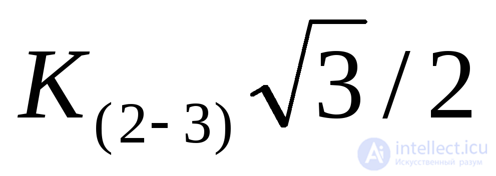 .
.
In the steady-state mode (t=∞), in which X1r=xd; X2r<<xd; X1res>>x2res,it can be assumed that X2res≈0. Then 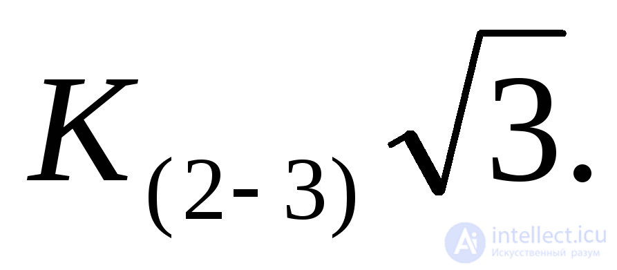 Consequently, the ratio K(2-3) lies within the following limits:
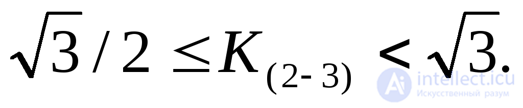
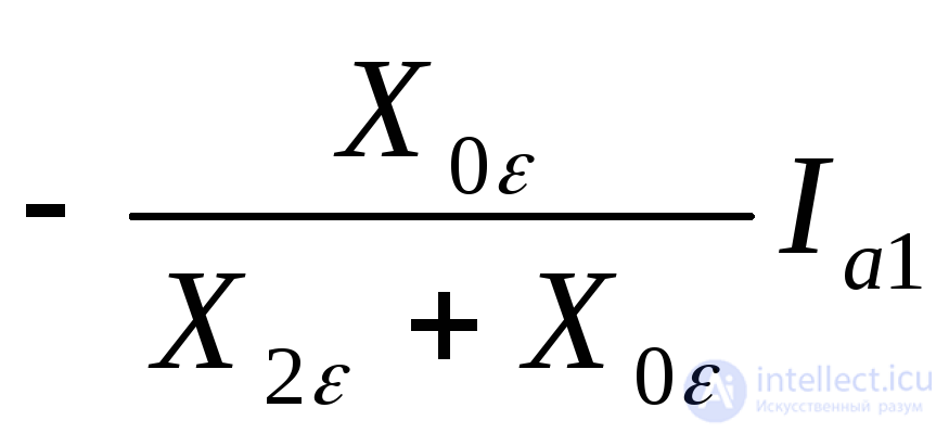
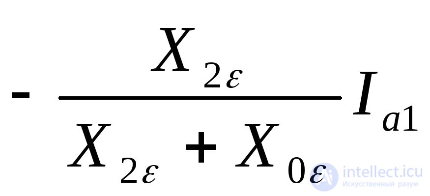
Table 7.1. Symmetrical components of currents and voltages at the point of short circuits
|
No. |
Name and designation of quantities |
Type of short circuit |
|||
|
Three-phase |
Two-phase |
Single-phase |
Two-phase to ground |
||
|
1 |
2 |
3 |
4 |
5 |
6 |
|
1 |
Positive-sequence current IA1 |
|
|
|
|
|
2 |
Negative-sequence current IA2 |
0 |
- IA1 |
IA1 |
|
|
3 |
Zero-sequence current I0 |
0 |
0 |
IA1 |
|
|
4 |
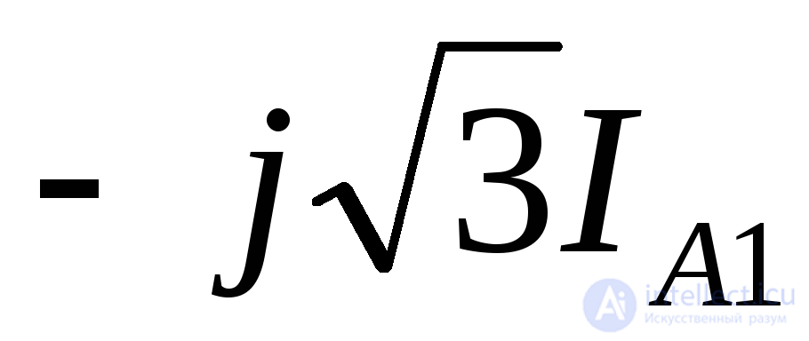
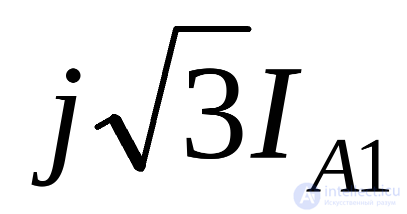
Total phase current:
IA
IB
IC |
Ia1
Ia1
Ia1 |
0
|
3 IA1
0
0 |
0
|
|
5 |
Positive-sequence voltage UA1 |
0 |
|
|
|
|
6 |
Negative-sequence voltage UA2 |
0 |
UA1 |
|
UA1 |
Continuation of Table 7.1
|
1 |
2 |
3 |
4 |
5 |
6 |
|
7 |
Zero-sequence voltage UA0 |
0 |
0 |
|
UA1 |
|
8 |
Total phase voltage: UA UB UC |
0 0 0 |
2 UA1 -UA1 -UA1 |
0
|
3 UA1 0 0 |
Note. a = - 0.5 + j 0.866, a2 = - 0.5 – j 0.866, a – a2 = j  , a2 – a = - j
  .
.
Table 7.2. Values of the additional resistance 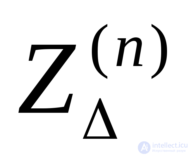 and the coefficient m(n)
|
Type of fault |
(n) |
|
m(n) |
|
Three-phase |
(3) |
0 |
1 |
|
Two-phase |
(2) |
|
|
|
Single-phase |
(1) |
|
3 |
|
Two-phase to ground |
(1,1) |
|
|
|
The same for |
(1,1) |
|
|
Note. To simplify the notation, the index 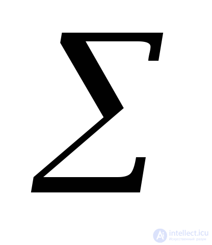 is omitted for the quantities
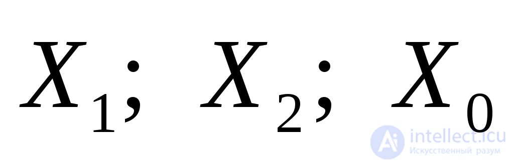 , which are the corresponding resulting impedances with respect to the point of the short circuit.
+It is important to note that the value of the positive-sequence current at the point of short circuit, as well as the associated values of the currents of the other sequences, depend on the impedances of all sequences of the elements of the circuit under consideration (including the arc resistance, when it is taken into account). Thus, for example, if the neutral of a transformer, at whose terminals there is a single-phase or two-phase short circuit to ground, is grounded through some resistance, this will affect the values of the currents of all sequences, although the positive- and negative-sequence currents do not flow through this resistance.
On the basis of equations (7.8), (7.22) and (7.30), a complex equivalent circuit can be formed for each type of short circuit by electrically connecting the circuits of the individual sequences. Fig. 7.5 shows such circuits, where, as a general case, the circuit of each sequence is characterized here by the corresponding full impedance (Z1, Z2, Z0). The equivalent circuits correspond to the special phase.
It must be kept in mind that in the complex circuit for a single-phase short circuit (Fig. 7.5) the correct values of the positive-sequence voltages at various points are ensured. As for the negative and zero sequences, they must be determined with respect to the zero-potential points of the circuits of the same-name sequences, i.e., respectively with respect to points N2 and N0, which are the origins of the circuits of these sequences.
Comparison of the types of short circuit
The rule of positive-sequence equivalence and the established values of 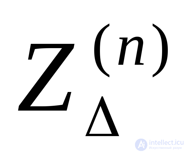 and
and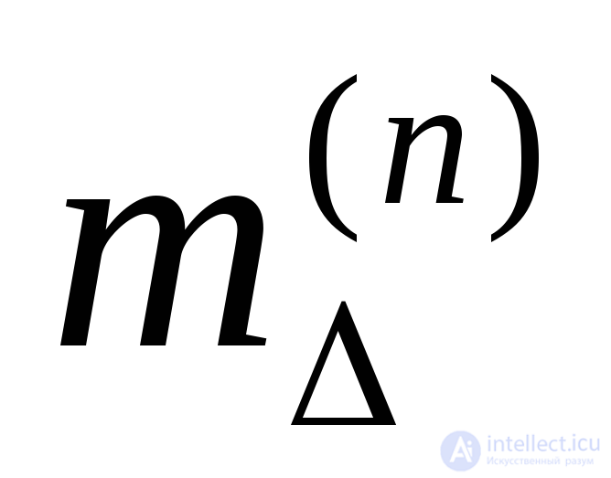 (Table 7.2) make it possible to compare the various types of short circuit quite simply.
Bearing in mind that short circuits occur in turn at the same point of the system and under the same initial conditions, it follows from Table 7.2 that between the values of the additional reactances 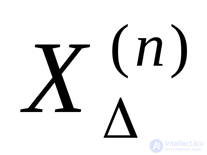 for various types of short circuit the following inequalities hold
 .
.
Accordingly
 and
and  .
.
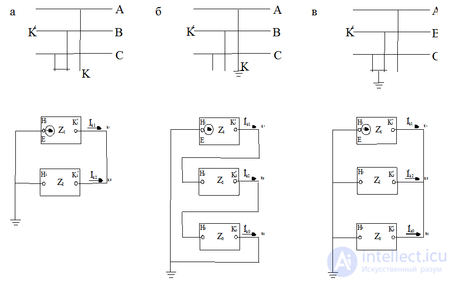
Fig. 7.5. Complex equivalent circuits: a – for a two-phase short circuit, b – for a single-phase short circuit, c – for a two-phase short circuit to ground
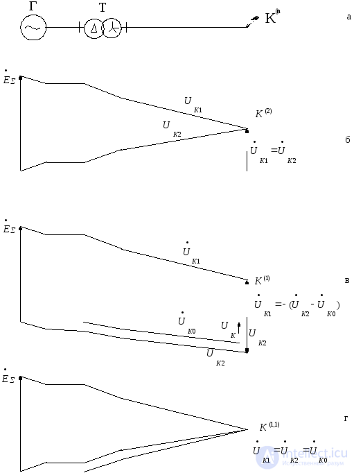
Fig. 7.6. Diagrams of the relative voltages of the individual sequences: a – schematic diagram, b – two-phase short circuit, c – single-phase short circuit, d – two-phase short circuit to ground
All the practical methods and techniques for calculating the transient process for a three-phase short circuit described earlier can, according to the rule of positive-sequence equivalence, be applied to the calculation of the transient process for any unsymmetrical short circuit. In most practical calculations of the initial instant of the unsymmetrical transient process, the positive-sequence circuit, with all its EMFs excluded, can be taken as the negative-sequence circuit; in this case it can be assumed that 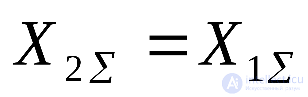 .
.
Since the positive-sequence voltage at any point of the circuit during an unsymmetrical short circuit is always higher than during a three-phase short circuit at the same point, the feeding effect of individual motors, or of the load as a whole, is weaker during unsymmetrical short circuits than during a three-phase short circuit. Therefore, when calculating the surge current of an unsymmetrical short circuit, it is often possible to neglect the loads and individual motors, with the exception only of sufficiently powerful motors directly connected to the point of short circuit.
When a more accurate accounting of the load is necessary, which occurs when determining the current distribution (chiefly for the purposes of relay protection), it is convenient to use the principle of superposing the preceding normal mode on the fault mode itself. The calculation of the latter for an unsymmetrical short circuit reduces to finding the currents and voltages in the complex circuit corresponding to the given asymmetry when it is energized with a voltage equal in magnitude and opposite in direction to the voltage that existed at the point of short circuit before it occurred. A further simplification in the calculation of such a mode, as is well known, consists in neglecting the resistances of the circuit elements. However, in an extended overhead and especially cable network it is often necessary to take into account the resistance of the lines, whose influence is particularly noticeable in a single-phase short circuit. The same must be said with regard to taking into account the current-limiting effect of the arc that arises at the point of short circuit.
Example 7.1. Estimate the degree of participation of the loads in the initial subtransient current for a two-phase short circuit at point K, and compare it with what would occur if a three-phase short circuit took place at the same point.
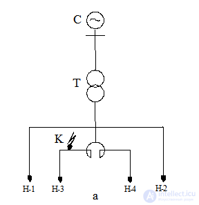
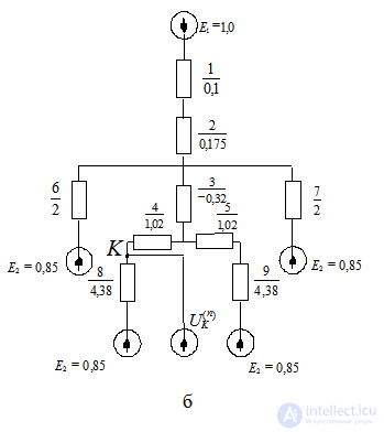
For Example 7.7:
a – original circuit,
b – positive-sequence equivalent circuit
Initial data:
C – system, 
R – double reactor 2*1000 A, 6 kV,
x = 8 %, coupling coefficient 0.46.
T – transformer 60 MVA, 115/6.3 kV,
Uk= 10.5 %
N-1, N-2 loads of 17.5 MVA each,
N-3, N-4 loads of 8 MVA each.
Fig. 7.7,b shows the positive-sequence equivalent circuit, where all the elements and EMFs are expressed in per-unit values at  .
.
The negative-sequence circuit in this case will be the same, except that in it all the EMFs will be equal to zero.
Let us transform the circuit to its simplest form:
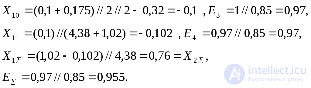
For a two-phase short circuit, the positive-sequence current at the point of short circuit is

and the positive-sequence voltage at the point of short circuit

Positive-sequence current in element 4:
 .
.
Positive-sequence voltage beyond this element:
 .
.
Positive-sequence current flowing into the load (element 9):
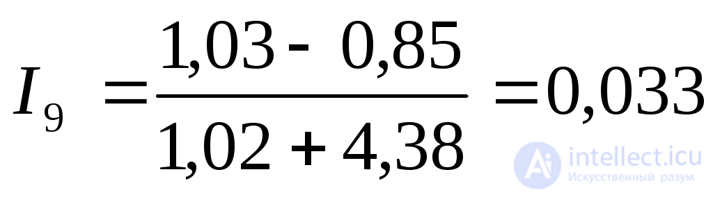 .
.
Positive-sequence voltage on the substation busbars:
 .
.
Consequently, loads N-1 and N-2 take no part whatsoever in the positive-sequence circuit, since there is no current of this sequence in them. The presence of the loads is reflected only in a very slight reduction of the resulting reactance 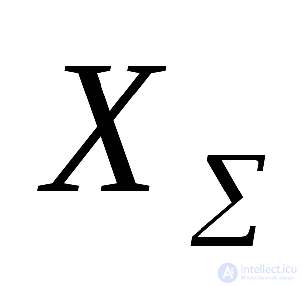 .
.
The initial subtransient current at the point of the two-phase short circuit will be:

or
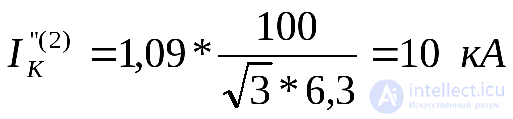 .
.
In this case, if load N-3 is excluded, this current would be:
 ,
,
i.e., the feed-in from load N-3 amounts to 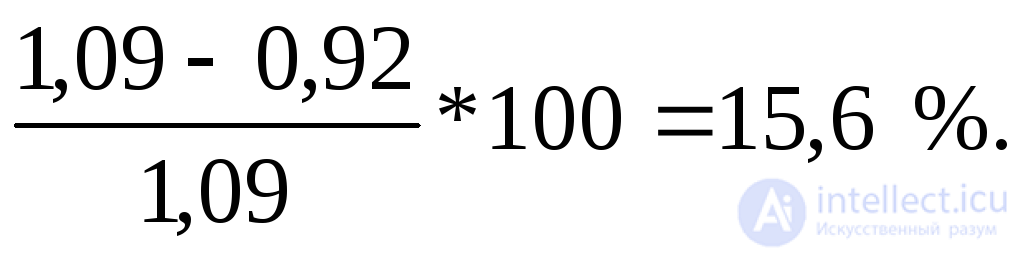
A similar calculation for a three-phase short circuit at the same point shows that the residual voltage on the substation busbars drops to U= 0.73 and the contribution of the loads to the subtransient initial current at the point of short circuit is approximately 25 %.
Example 7.2. When an induction motor M, fed from the 6 kV busbars of a step-down substation (Fig. 7.8,a), was switched in, one phase remained open due to a fault in breaker Q. For these conditions, determine the magnitude of the initial starting current and estimate to what extent this will affect the torque of the other induction motors fed from the same busbars.
The system is characterized by a constant voltage of 115 kV, applied behind a reactance
x1= x2=26.4 Ohm.
Transformer: T 10 MVA, 115/6.3 kV, Uk= 10 %.
Induction motor M 4000 kW, 6kV,  , efficiency =0.92,Istart= 4.5. Load N 2.5 MVA.
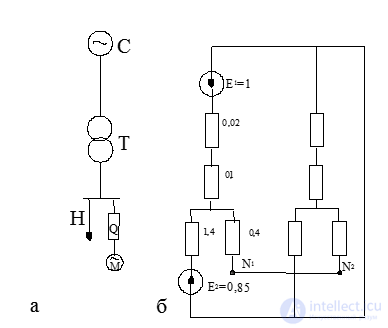
Fig. 7.8. For Example 7.2:
a – original circuit, b – complex equivalent circuit
Start of the motor on two phases can be regarded as a two-phase short circuit behind the reactance of the stalled motor, which is the same in the positive and negative sequences. Thus, for the given conditions, the complex circuit has the form shown in Fig. 7.8,b, where N1and N2– are the neutral points of the motor stator winding in the positive-sequence and negative-sequence circuits, respectively. The reactance and EMF values shown in the diagram, in per-unit terms, are at . Correspondingly,
 .
.
Solution:
Rated apparent power of the motor:
 .
.
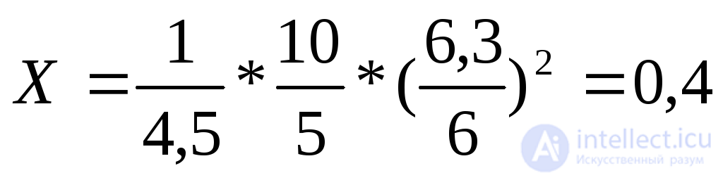
Motor reactance under base conditions:
 .
.
Resultant reactances relative to points N1and N2:
 .
.
Resultant EMF
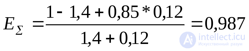 .
.
Positive-sequence component of the starting current:
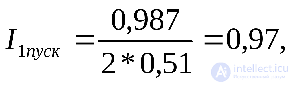
and the starting current magnitude under base conditions

and under the motor's rated conditions

i.e., it is lower than the rated starting current by 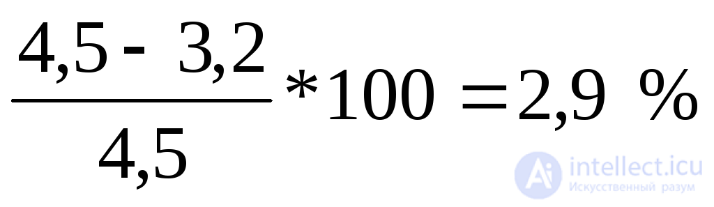 .
.
Symmetrical components of the bus voltage:
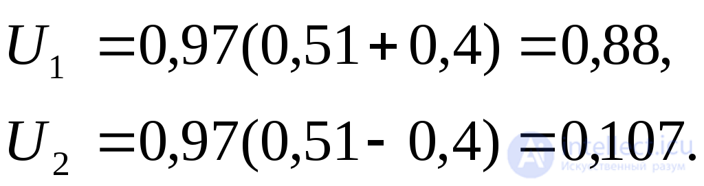
Considering that the torque due to the negative-sequence voltage at the operating slip is negligibly small, the torque of the motors fed from the bus over three phases will practically be:
 ,
,
i.e., it will decrease by 14%.
As for the motor connected through two phases, the voltage components at its terminals will be:
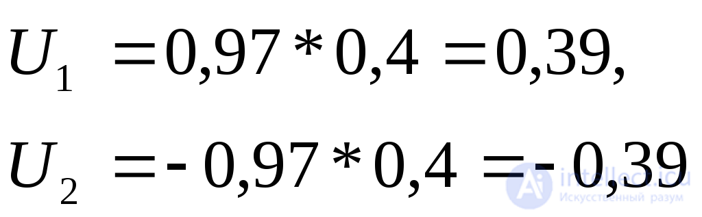
and the motor's starting torque, as expected, Mstart= 0.
Example 7.3. On the line of the diagram (Fig. 7.9) a solid short circuit occurred between phases «B» and «C», with a simultaneous fault of the common point to ground through an arc. Determine the currents and voltages at the beginning of the line for the initial disturbance.
Generator G 60 MVA; 10.5 kV;  was previously operating at no load with rated voltage.
Transformer T 60 MVA; 154/10.5 kV; Uk =10 %.
Line L  .
.
Arc resistance rg = 9.5 Ohms.
Let us take as base conditions  . Then the line resistances in relative base units will be:

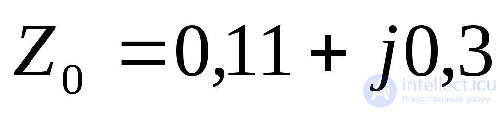
and the arc resistance: rg = 0.04.
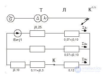
Fig. 7.9 shows the complex equivalent circuit for the case under consideration. The resultant impedances of the individual sequence circuits are:
Fig. 7.9. For Example 7.3
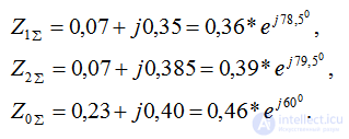
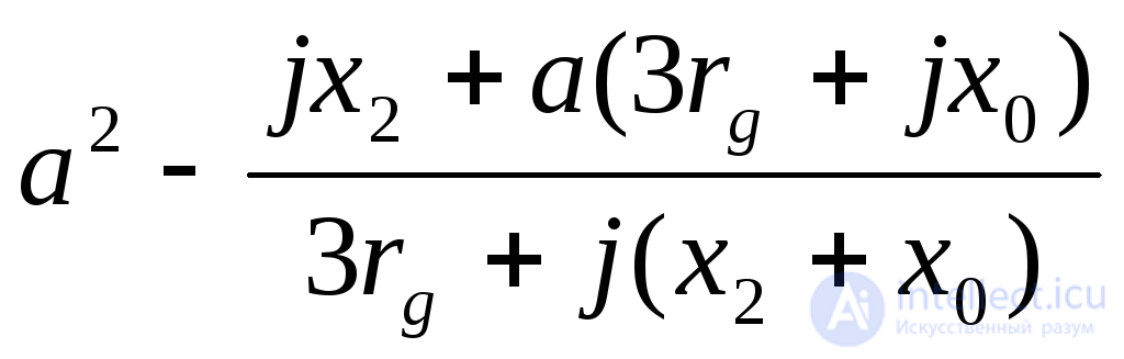
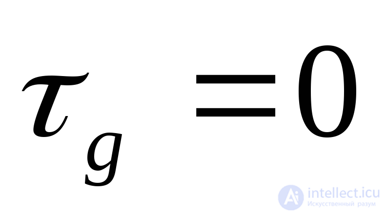
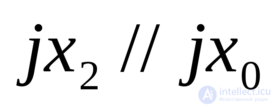
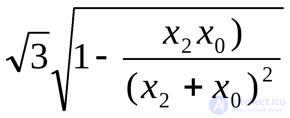
Additional resistance:
 .
.
Total resistance for this type of fault:
 .
.
Symmetrical components of the currents at the fault location (which in this case are also the symmetrical components of the line phase currents)
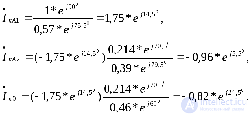
The symmetrical components of the voltages at the beginning of the line are easier to determine here by proceeding, in the circuit of each sequence, from the point of zero potential, i.e.
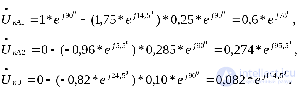
Once the symmetrical components of the currents and voltages have been found, obtaining the phase currents and voltages is no longer difficult, either with the help of a vector diagram or analytically.



Comments