
Lecture
A series (longitudinal) asymmetry at any point of a system can, in general, be represented by inserting unequal impedances into each phase, and these impedances may additionally be coupled by mutual inductance, the value of which also differs for each pair of phases.
As noted earlier, this approach to solving the problem makes it possible in principle to obtain calculation expressions for determining currents and voltages in the most general form. However, it is considerably simpler and more illustrative to carry out the solution for each type of series asymmetry using the boundary conditions that characterize it.
Here, considering only the fundamental harmonic of the mode, the following conditions are used as a basis: inserting an impedance into a phase, with the supply source EMF unchanged, is equivalent to shunting the same impedances in the other phases; shunting in a phase is equivalent to inserting the same impedance but with the opposite sign; and a break in a phase is equivalent to inserting, at the point of the break, a voltage source equal to the voltage drop across the terminals of the broken phase.
As with shunt (transverse) asymmetry, in calculating series asymmetry it is effective to apply the method of symmetrical components, according to which the calculation expressions can be expressed through the symmetrical components of the current and voltage of phase «A», taken as the reference (special) phase.
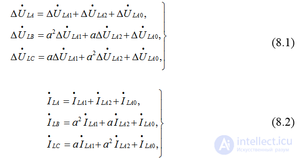
where  – are the currents and voltage drops for the asymmetrical system of phase quantities A, B and C;
 –the symmetrical components of the currents and voltage drops of the positive, negative and zero sequences.
Currents of a given sequence give rise to voltage drops of the corresponding sequence. This relationship between them is described by a system of independent equations
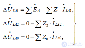 (8.3)
(8.3)
where 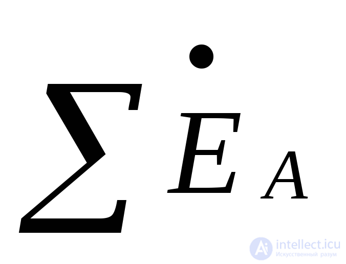 – is the total EMF of the supply sources, present only in the positive-sequence circuit;
 – are the resultant impedances of the individual sequences relative to the point of the series asymmetry.
Thus, as with shunt asymmetry, the method for obtaining the calculation relations is based on solving the system of equations (8.1)–(8.3), taking into account the boundary conditions that characterize the asymmetry.
This section considers two types of the most commonly encountered series asymmetry: a break in one phase and a break in two phases (at the same location).
An actual circuit with a single series asymmetry is reduced to equivalent circuits without a break. This is achieved by introducing, at the point of the fault, a series voltage source whose value equals the voltage drop at the point of the series asymmetry.
In an electrical system, shunt and series asymmetries can occur simultaneously in various combinations, leading to complex types of faults. In this case, the sequence of computational operations is repeated at each point of asymmetry.
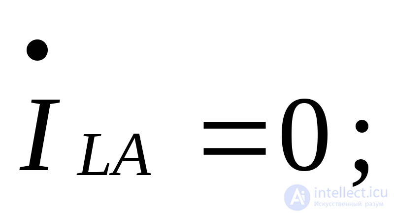
A break in one phase can be characterized by the boundary conditions
 (8.4)
(8.4)
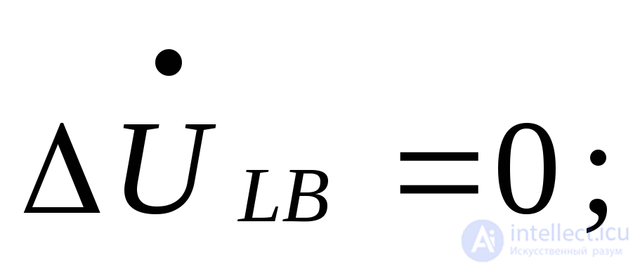 (8.5)
(8.5)
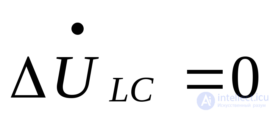 , (8.6)
i.e., they are analogous to the boundary conditions of a two-phase short circuit to earth.
When decomposed into symmetrical components, conditions (8.5) and (8.6) lead to the equalities
 (8.7)
(8.7)
Using (8.3) and (8.7), let us express 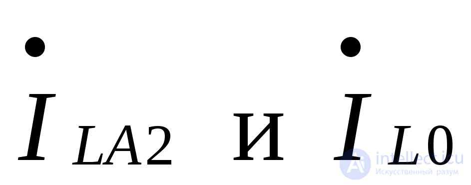 as
as
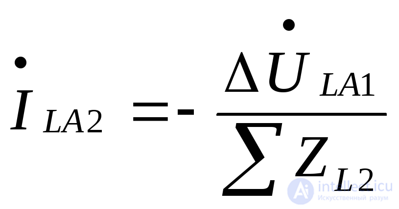 (8.8)
(8.8)
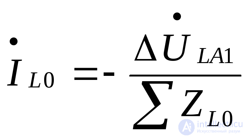 , (8.9)
After substituting (8.8) and (8.9) into (8.4), we obtain
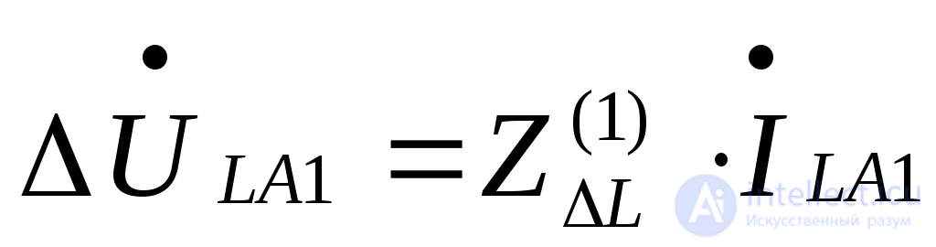 . (8.10)
where
 . (8.11)
For the positive-sequence current of phase «A» at the point of the break, taking (8.3) and (8.10) into account, we obtain
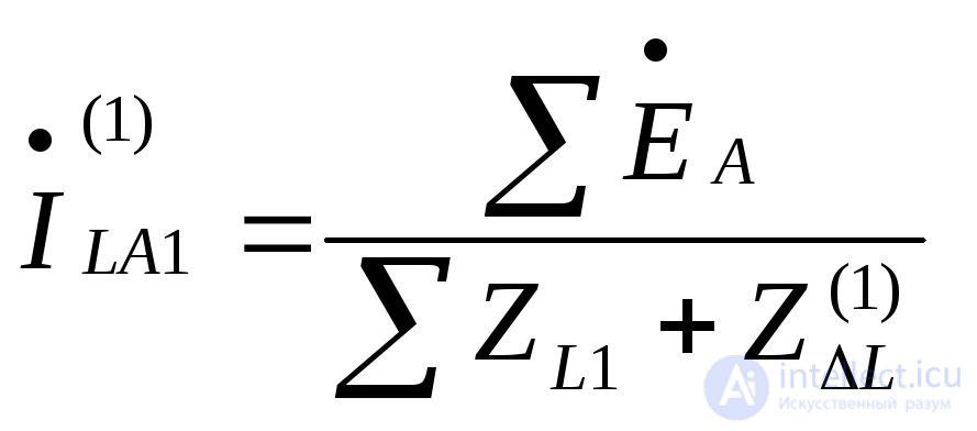 . (8.12)
The expressions for 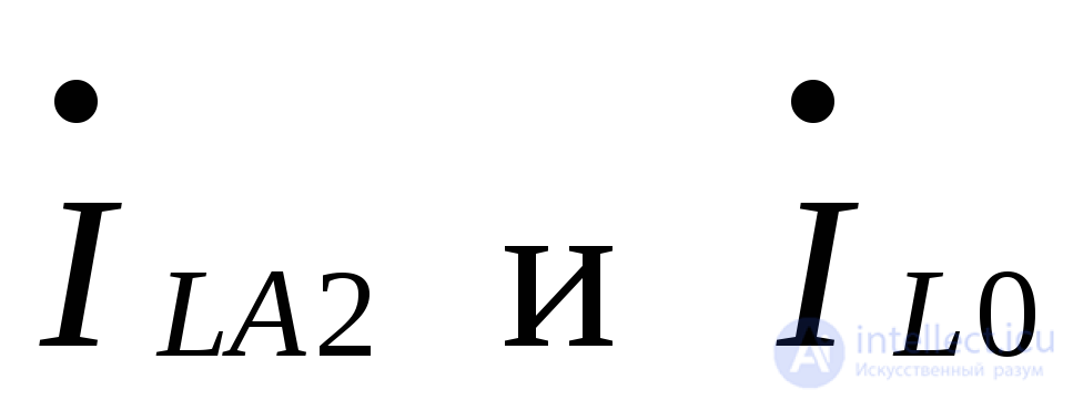 obtained similarly are given in Table 8.1.
To determine the voltages on one side of the series asymmetry, the corresponding components of these voltages should first be found from the circuits of the individual sequences of the symmetrical part of the circuit. By adding 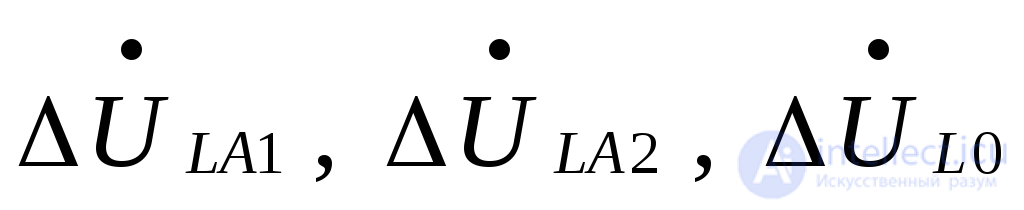 to the latter, the symmetrical components of the voltages on the other side of the series asymmetry are found. Knowing the symmetrical components of the currents and voltages (Table 8.1), the phase values of the currents and voltages can be obtained using expressions (8.1) and (8.2).
It should be noted that the initial equations used in deriving the expressions for calculating the currents and voltages for a break in one phase are absolutely analogous to those for the case of a two-phase short circuit. Therefore, the calculation formulas obtained there can be used to calculate the currents and to find the magnitude of the phase currents when analyzing the break of one phase.
For illustration, Fig. 8.1, b, c, d show vector diagrams of the currents and voltages at the point of the break of one phase «A».
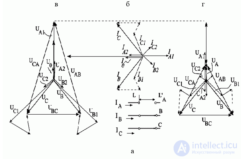
Fig.8.1. Break in one phase of a three-phase circuit: a – original circuit, b – vector diagram of the currents at the break point of a purely inductive circuit, c and d – vector diagrams of the voltages at the ends of the break (at points L and L’, respectively).
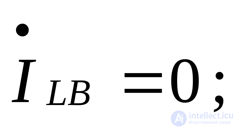
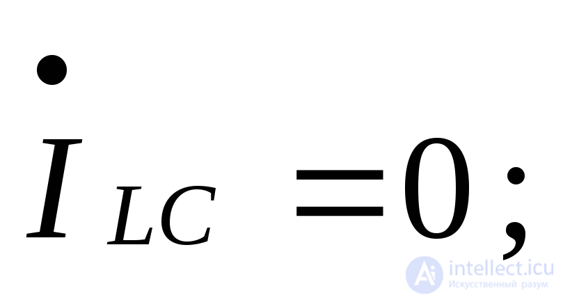
When two phases of a three-phase circuit break (Fig. 8.2), the boundary conditions are:
 (8.13)
 (8.14)
 . (8.15)
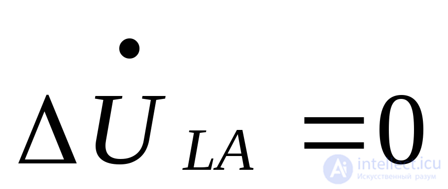
These conditions are analogous to the boundary conditions of a single-phase short circuit, and this analogy will also be reflected in the calculation expressions.
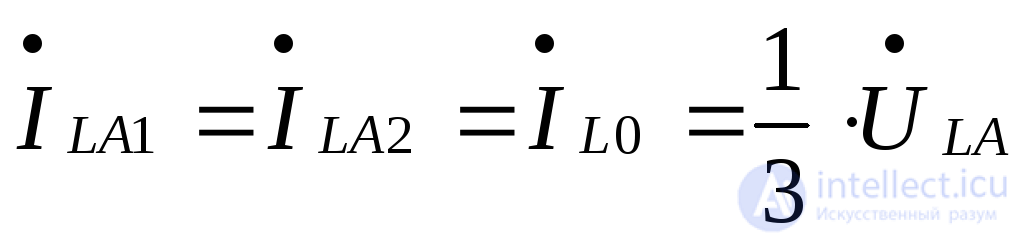
From (8.13) and (8.14) it follows that the symmetrical components of the current of phase «A» at the point of the break are related by
 . (8.16)
On the other hand, according to (8.15)
 . (8.17)
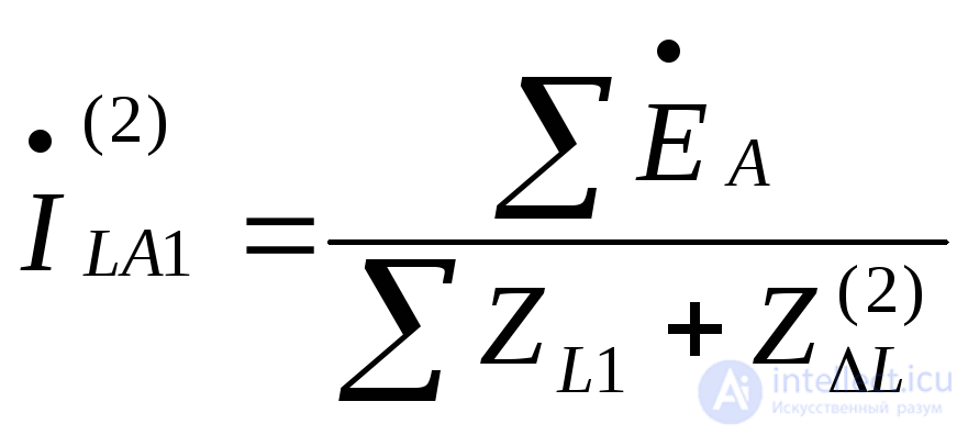
If the right-hand sides of equations (8.3) are added and the sum is set equal to zero, then, taking (8.16) into account, we obtain
 , (8.18)
where
 . (8.19)
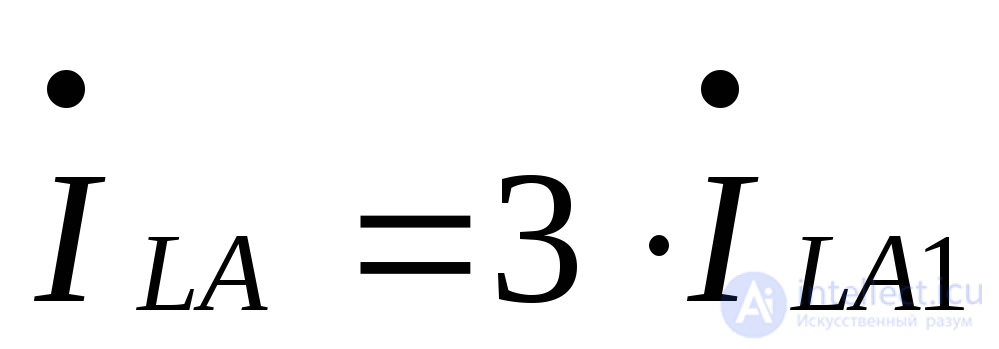
For the phase current, according to (8.16), we have
 (8.20)
The symmetrical components of the phase voltage difference at the point of the break are determined for the negative and zero sequences from (8.3), and for the positive sequence from (8.17)
 . (8.21)
Fig. 8.2 (b, c, d) shows vector diagrams of the currents and voltages at the point of the break of phases «B» and «C».
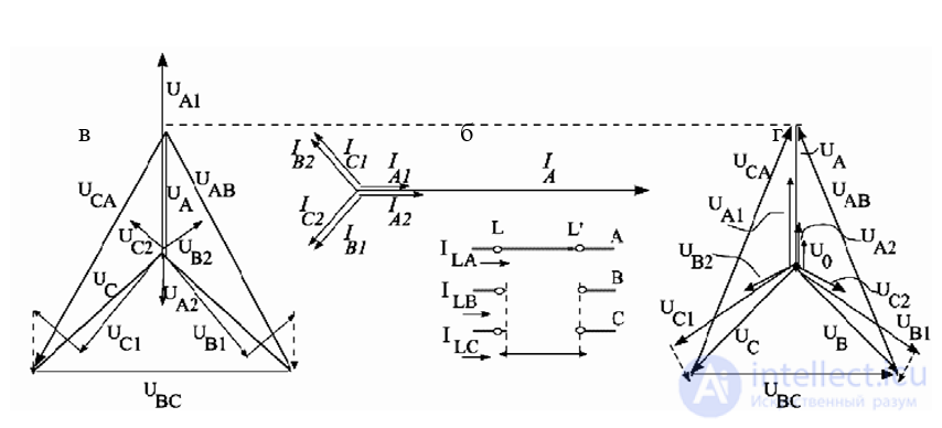
Fig. 8.2. Break of two phases of a three-phase circuit: a – original circuit, b – vector diagram of the currents at the point of the break, c and d – vector diagrams of the voltages at the ends of the break (at points L and L`
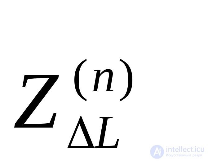
Let us consider cases in which identical impedances  are inserted into one or two phases (Fig. 8.3, a, c). Such conditions can arise, for example, in the case of non-simultaneous separation of the switch contacts.
Inserting impedances into one or two phases can be regarded as shunting the same impedances in the other two phases or in the third phase, respectively (Fig. 8.3, b, d), provided that in such a substitution the sources are characterized by the EMF values they had in the actual preceding mode.
For the insertion of impedance  into one phase of a three-phase circuit, the boundary conditions are
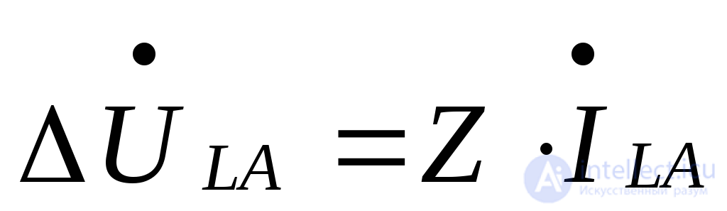 , (8.22)
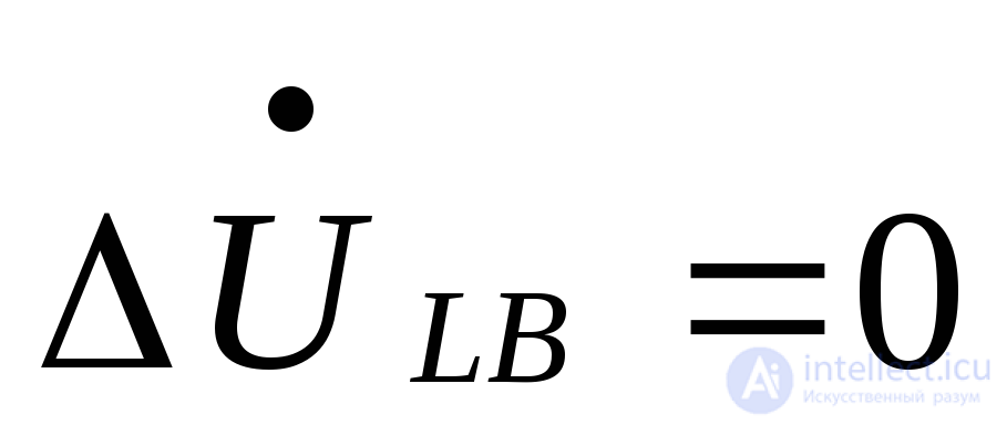 , (8.23)
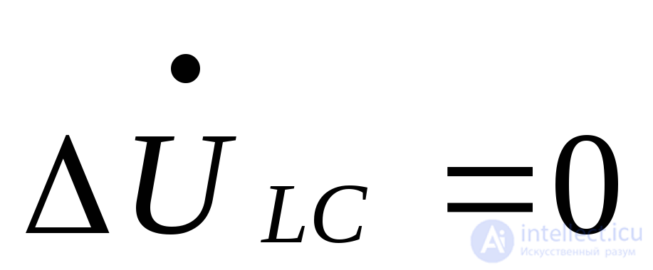 . (8.24)
Expressing (8.22) through symmetrical components and using (8.3) and (8.7), we obtain the expression for the additional impedance in the positive-sequence circuit
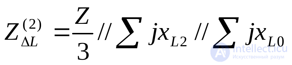 . (8.25)
When identical impedances are inserted into only two phases, for example «B» and «C», the following constraints must be introduced to characterize this asymmetry
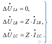 (8.26)
In this case, the expression for the additional impedance introduced into the positive-sequence circuit is
 . (8.27)
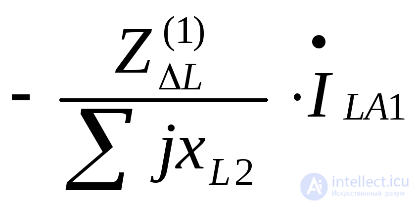
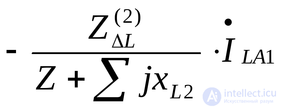
The calculation expressions for the symmetrical components of the currents and voltage drops at the point of a series asymmetry caused by the insertion of an impedance into one or two phases are given in Table 8.1. A break in one or two phases is a special case of such an asymmetry; the calculation expressions for it are obtained from those given in Table 8.1 by setting 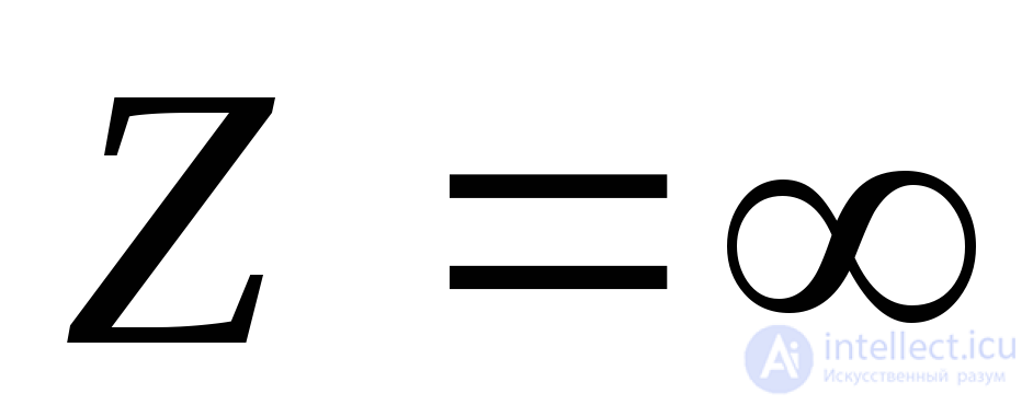 .
.
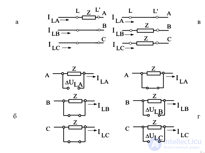
Fig. 8.3. Asymmetry due to inserted impedances: a, b – in one phase; c, d – in two phases
Table 8.1. Symmetrical components of the currents and voltage drops at the point of a single series asymmetry
|
Quantities to be determined |
When impedances Z are inserted |
|
|
into one phase |
into two phases |
|
|
|
|
|
|
|
|
|
|
|
|
|
|
|
|
|
|
|
|
|
|
|
|
|
|
|
|
|
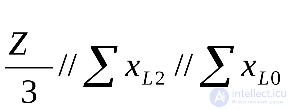
The expressions obtained above between the symmetrical components of the voltage drops at the point of the series asymmetry under consideration make it possible to construct a complex equivalent circuit for each type of asymmetry.
Such circuits are shown in Fig. 8.4, a, b; for the second case, two connection variants are shown: when the impedances 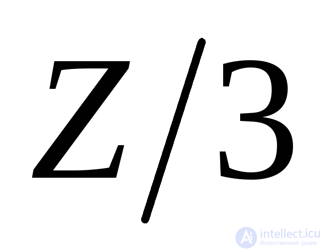 are connected in star, and when the impedances
 are connected in delta.
As with a single shunt asymmetry, these complex circuits correspond to the special phase, which, as usual, is taken to be phase «A».
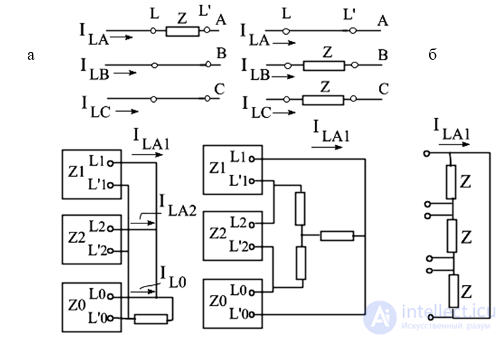
Fig. 8.4. Complex equivalent circuits: a – with an impedance in one phase, b – in two phases
Example 8.1.
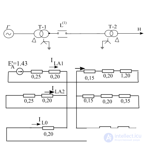
For the circuit of Fig. 8.5, a, determine the currents in the line when the wire of one of its phases breaks.
All elements are expressed in per-unit values, at the base conditions. The (complex) equivalent circuit is shown in Fig. 8.5, b.
The resultant reactances of the individual sequences relative to the point of the break are
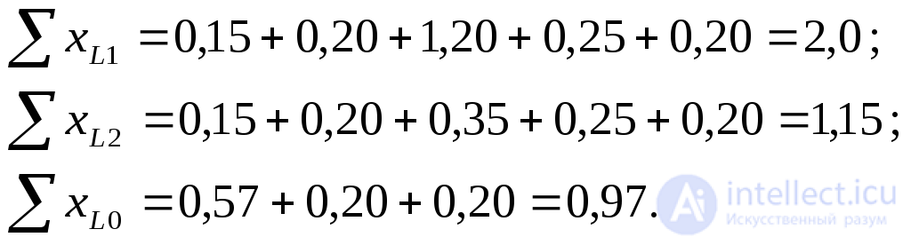
Additional reactance
 .
.
a
b
Fig. 8.5. For Example 8.1: a – original circuit, b – complex equivalent circuit
Symmetrical components of the currents at the point of the break:

Current in the undamaged phases of the line:
 .
.
As noted in 8.2, to determine the magnitude of the current in the undamaged phases, the coefficient 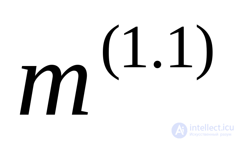 (Table 7. ) can be used, i.e.
 .
.
For comparison, note that under normal operation of the line the phase current is 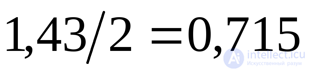 . Consequently, when one phase breaks, the current in the “healthy” phases increases by
 (with the same connected load maintained).
Example 8.2
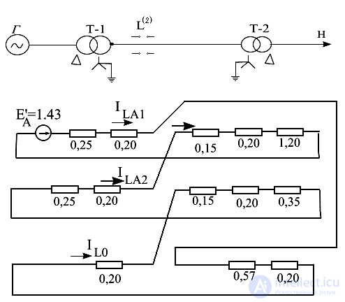
For the same circuit (Fig. 8.6, a) as in the previous example, determine the current in the line when two of its phases break.
a
b
Fig. 8.6. For Example 8.2: a – original circuit, b – complex equivalent circuit
Using the values 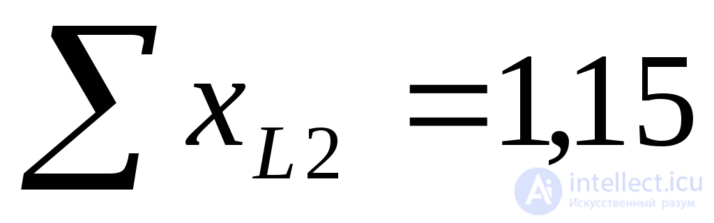 and
and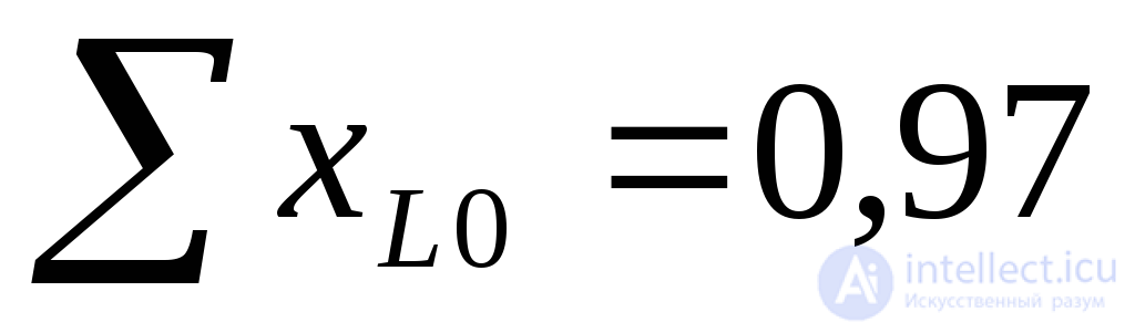 obtained in the previous example, we find the additional reactance for the break of two phases
 .
.
If 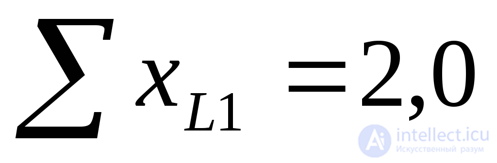 , the symmetrical components of the current of the undamaged phase will be

and, correspondingly, the phase current of the line 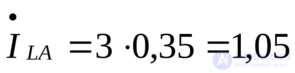 ,
,
i.e., it is 47% greater than under normal operation of the line.
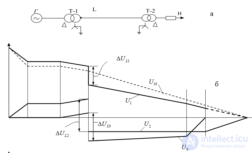
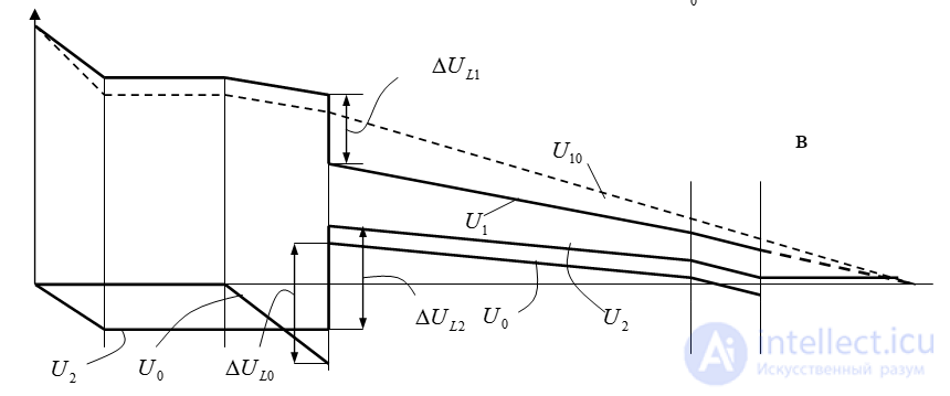
Fig. 8.7. Voltage distribution plots of the individual sequences: a – original circuit, b – plots for the break of one phase, c – for the break of two phases
Finding the symmetrical components of the currents and voltages is entirely solved on the basis of the corresponding complex circuit. Here, a certain peculiarity of series asymmetry should be kept in mind, namely that whereas the positive-sequence voltages at the ends of the asymmetrical section differ only in magnitude, the negative- and zero-sequence voltages also differ in sign. Fig. 8.7, b, c show the voltage distribution plots of the individual sequences. The dashed line shows the voltage plot under normal operation.
In a circuit with single-end supply (Fig. 8.7, a), when one phase breaks (Fig. 8.7, b), the positive-sequence voltage beyond the point of the break is significantly higher than for the break of two phases (Fig. 8.7, c). Before the point of the break, conversely, the voltage is somewhat higher in the latter case.
The negative- and zero-sequence voltages for the break of one and two phases are opposite in sign. As the distance from the point of series asymmetry increases, the degree of distortion of the voltage vector diagram decreases, since the relative contribution of the positive-sequence voltage component increases even with increasing distance from the supply source.
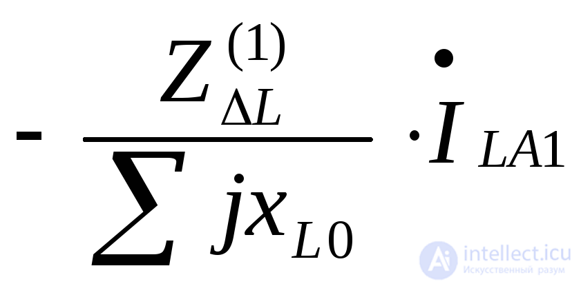
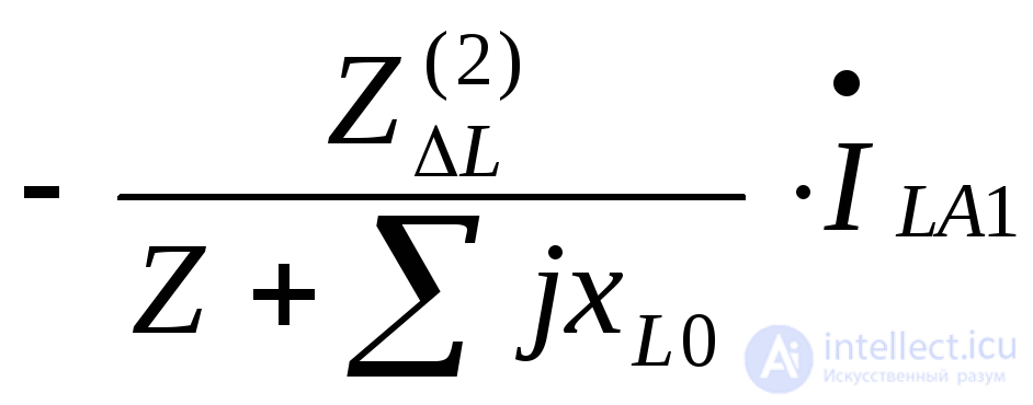
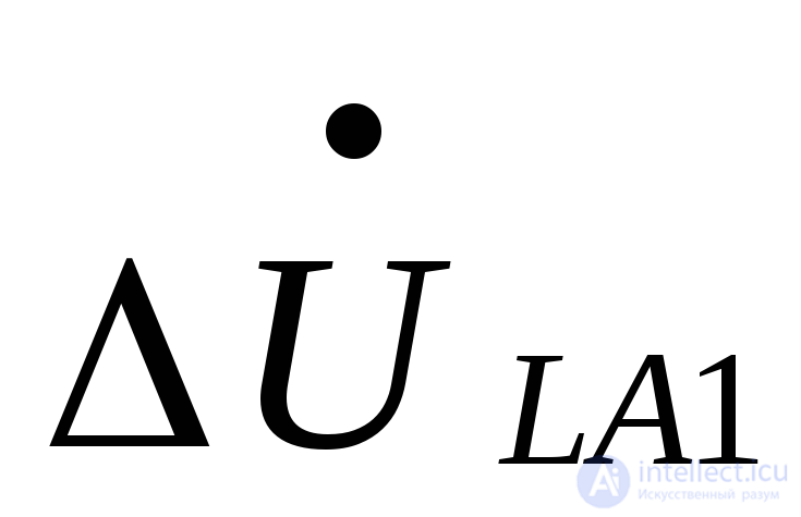
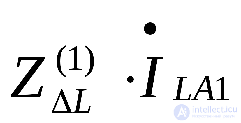
When the preceding mode, in which the break of one or two phases occurred, is known, it is convenient to determine the currents and voltages after the break using the superposition principle. The incomplete-phase mode can be represented as the result of superimposing, on the preceding mode, the actual fault mode proper, determined under the condition that a current source is introduced at the point of the break (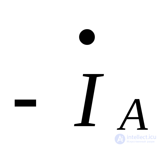 ) and all EMFs are removed from the circuit.
The current source is inserted at the point of the break in the positive-sequence circuit. The current distribution and the potentials at different points, obtained in the negative- and zero-sequence circuits of the corresponding complex circuit of the actual fault mode when a current source (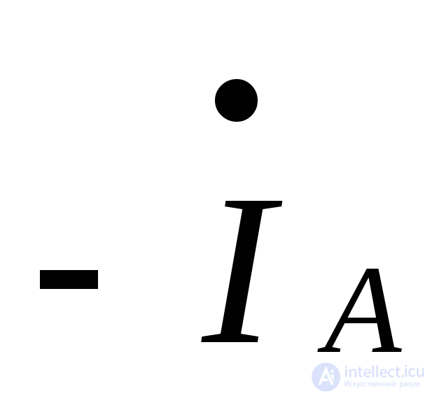 ) is introduced at the point of the break, determine the values of the negative- and zero-sequence currents and voltages. To find the positive-sequence current in any branch, the actual fault positive-sequence current obtained for that branch must be added to its preceding current. The same procedure should be followed when determining the positive-sequence voltages. From this form of the superposition principle it directly follows that the larger the preceding current in a circuit where a break of an incomplete number of phases is subsequently assumed to occur, the correspondingly larger the fault components will be, and the more strongly the symmetry of the currents and voltages will be distorted.
Example 8.3
For the circuit (Fig. 8.8, a), construct the vector diagrams of the currents in both circuits of the line for the break of the wire of phase «A» of circuit I. The preceding phase currents of each line circuit are 305 A.
We solve using the superposition principle. The complex equivalent circuit for the actual fault mode of the given circuit is shown in Fig. 8.8 (b). The reactances of all its elements are expressed in ohms and referred to the voltage level at which the line is located.
The resultant impedances of the individual sequence circuits are:  .
.
The resultant inductive reactance of the circuit relative to the current source:  .
.
The actual fault component of the positive-sequence current at the point of the break:
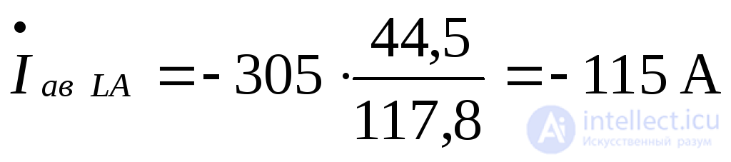 .
.
The negative- and zero-sequence current components at the point of the break:
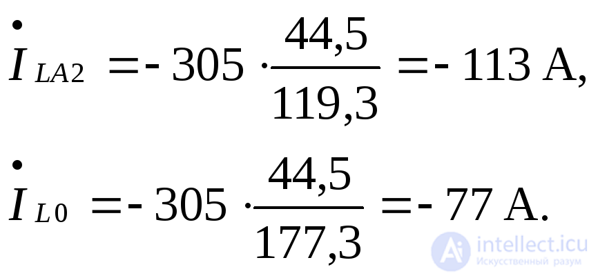
The distribution of these currents in the circuits of the corresponding sequences is shown in Fig. 8.8, b.
Using the current components found, the vector diagrams of the currents in the first and second circuits of the transmission line are constructed in Fig. 8.8, c.
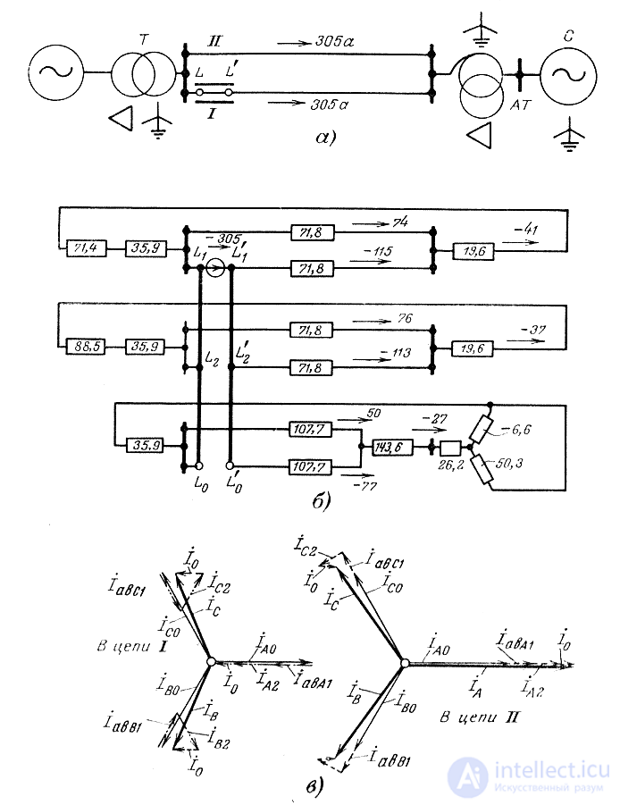
Fig. 8.8. a – original circuit, b – complex equivalent circuit for the actual fault mode (with a current source at the point of the phase break),
c – vector diagrams of the currents in the line circuits





Comments