
Lecture
The solution of the wave equations is considerably simplified if a semi-infinite long line is considered under harmonic excitation e(t) = Em cosωt .
In such a line there are no conditions for the propagation of a reverse wave, so only the forward wave exists; it is called the incident wave.
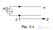
• The steady-state processes in such a line at an arbitrary cross-section are harmonic, but a phase shift appears, which is related to the finite propagation
velocity of the wave. The voltage and current at any cross-section are determined from the relations:
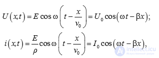
where v0 = λ/T = (L0C0)–2 – is the signal propagation velocity in the long line;
• β = ω/v0 – is the phase coefficient; it characterizes the phase shift of the wave per unit length of the line, sometimes called the spatial frequency of the signal, since β = 2π/λ , where λ – is the wavelength (this name is given by analogy with the fact that ω = 2π/T –is the temporal frequency).
• The ratio of the complex amplitude of the voltage to the complex amplitude of the current of the forward wave is called the characteristic impedance of the line Zw = Um / Im. In a lossless line it is purely resistive in character –ρ, and is called the characteristic resistance.
(v0, β, Zw) - are called the wave, or secondary, parameters of the long line.
Thus, in a lossless long line the signal at any cross-section does not change its shape or amplitude, but a delay is observed due to the finite velocity. In a lossy line, not only a time delay is observed, but also an attenuation
of the signal amplitude as x increases.
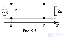
• In practice, lines Zn of finite length are often used. Let a uniform line of length L be loaded at its end (x = L) with an impedance Zn.
At x = 0 the line is fed from a harmonic EMF generator with internal resistance Ri.
•The characteristic impedance of the line Zw = ρ.
• In harmonic oscillation, the instantaneous value of the voltage at any point is determined by the sum of the incident and reflected voltage
waves,
while the instantaneous values of the current are determined by the difference between the incident and
reflected current waves. The signs in the sums are related to the fact that the positive directions of the voltages Uinc
Uref are chosen the same (top to bottom), while for the currents Iinc, Iref – they are opposite, so they are subtracted:
U(x,t) = Uinc+ Uref;
I(x,t) = Iinc – Iref,
where U(x,t),Uinc, Uref , I(x,t) , Iinc, Iref – are complex amplitudes.
• The processes occurring in a long line are determined not only by the wave parameters, which characterize the intrinsic properties of the line, but also by the reflection coefficients, which depend on the matching of the line with the load.
• In the steady state, two waves are present in the line. These waves propagate in two mutually opposite directions. The wave traveling from the generator to the load is called the forward, or incident, wave. The wave traveling from the load to the generator is called the reverse, or
reflected, wave. The appearance of the reverse wave is due to the reflection of the incident wave from the load. Thus, in a long line, at every instant of time, at every point of the cross-section, there is present the algebraic sum of two waves – incident and reflected.
• The complex reflection coefficient of a long line is the ratio of the complex amplitudes of the voltages and currents of the reflected and incident
waves at an arbitrary cross-section of the line:
• complex voltage reflection coefficient;
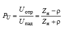
• complex current reflection coefficient.
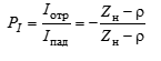
• Depending on the ratio between the characteristic impedance ρ and the load impedance Zn, a long line can operate in three modes:
• 1. Traveling-wave mode occurs in the line when only the incident voltage and current waves propagate, while
the reflected wave is zero at every cross-section. All the energy from the source is delivered to the load in this mode, there is no reflection, hence Uotr = 0 and Pu = 0.
• 2. Standing-wave mode occurs when the wave is completely reflected from the load, i.e., two waves of equal amplitude are simultaneously
present in the line: Uotr = Upad, hence |Pu| = 1. In this mode energy is
not delivered to the load.
• 3. Mixed-wave mode. In this mode part of the energy is delivered to the load and part is reflected, i.e., in the line
two waves of unequal amplitude are simultaneously present.
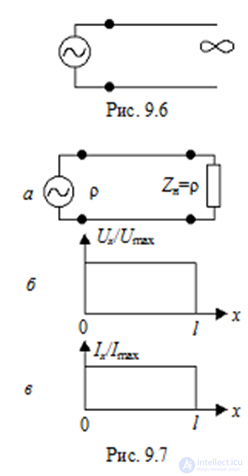
Traveling-wave mode is possible for the following types of load:
• a) a semi-infinite long line (Fig. 9.6). It has no end, and therefore no reflected wave. Fig. 9.6
• b) the line is loaded with an impedance equal to the characteristic impedance, Zn = ρ (Fig. 9.7, a).
• The reflection coefficient is zero 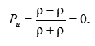
• In a lossless line, in traveling-wave mode the distribution of voltage and current amplitudes along the line is constant
(Fig. 9.7, b, c), while in a lossy line the voltage and current amplitudes decay exponentially.
• The input impedance of the line in traveling-wave mode equals the characteristic impedance of the line and does not depend on its length.
• In traveling-wave mode, energy transfer occurs only in one direction – from the source to the load, such a
load is called matched.
In this mode the entire incident wave is reflected from the load. The power delivered to the load is zero. Standing-wave mode, Pu = 1, occurs in the following three cases (Fig. 9.8):
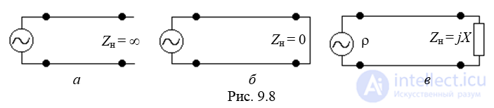
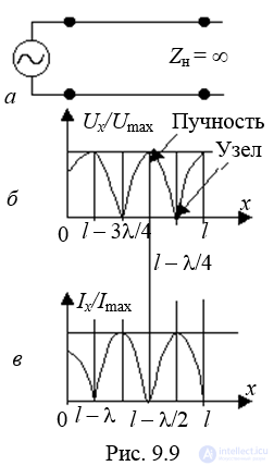
1) an open-circuited line, Zn = ∞.
2) Zn = 0
3) Zn = jX
The voltage reflection coefficient Pu = 1. This means that at the end of the line the voltage wave is fully reflected, i.e., the amplitude of the incident wave equals the amplitude of the reflected wave, and the sign of the reflected wave matches that of the incident wave, which causes the voltage at the end of the line to double.
The current reflection coefficient Pi = –1. This means that the current at the end of the line is zero.
The distribution of voltage and current amplitudes along the line in open-circuit mode is shown in Fig. 9.9, b.
Points of maximum voltage or current are called antinodes of voltage or current, while points where the voltage or current amplitude is zero are called nodes.
In open-circuit mode there is a voltage antinode and a current node at the end of the line.
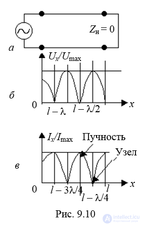
b) a short-circuited line at the end: Zn = 0. Reflection coefficients 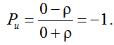 . Pi = 1.
Graphs of the voltage and current amplitude distribution are shown in Fig. 9.10, b, c. There is a current antinode and a voltage node at the end of the line.
c) the line is loaded with a reactive impedance Zn = jX.
The reflection coefficients 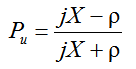 and
and 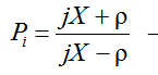 are complex quantities, and their magnitudes are equal: │Pu│=│Pi│=1. This means that the amplitudes of the forward and reflected waves in the line are equal, but there is neither an antinode nor a node at the end.
3) Mixed-wave mode.
In this mode the incident wave is partially absorbed and partially reflected. It occurs in the following cases:
a) the load is a complex impedance:
Zn = Rn + jXn Um min Um max.
b) the load is a resistive impedance not equal to the characteristic impedance ρ:
Zn = Rn ≠ ρ.
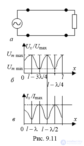
In mixed-wave mode the amplitude of the reflected wave is smaller than the amplitude of the incident wave. Hence, │Pu│=│Pi│<1, and therefore the current and voltage amplitudes at the minima are not zero. Fig. 9.11, b, c shows the distribution of voltage and current amplitudes along the line in mixed-wave mode for a purely resistive load (Rn > ρ).
The reflection coefficient is convenient for theoretical analysis, but it is difficult to determine experimentally, since it is difficult to separate and individually measure the amplitudes of the incident and reflected waves. Therefore, in practice, the operating mode of a long line and the degree of its matching with the load are characterized by the following coefficients:
1) Traveling wave ratio (TWR):
TWR = Um min/Um max,
where Um min, Um max – are the minimum and maximum values of the voltage amplitude along the line.
2) Standing wave ratio (SWR):
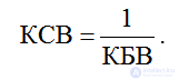 .
.
In traveling-wave mode, TWR = 1, SWR = 1.
In standing-wave mode, TWR = 0, SWR = ∞
In mixed-wave mode, 0 < TWR < 1, 1 < SWR < ∞.

Comments