
Lecture
Resonance is the operating mode of a circuit containing inductive and capacitive elements in which its input impedance (input admittance) is purely real. A consequence of this is that the current at the circuit input is in phase with the input voltage.
Resonance in a circuit with series-connected elements
(voltage resonance)
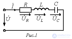
For the circuit in Fig. 1 we have

where
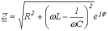 ; ; |
(1) |
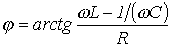 . . |
(2) |
Depending on the relationship between the values  and
and  , three different cases are possible.
1. Inductance dominates in the circuit, i.e.  , and consequently
 . This mode corresponds to the phasor diagram in Fig. 2,a.
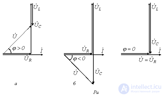
2. Capacitance dominates in the circuit, i.e.  , and hence
  . This case is reflected by the phasor diagram in Fig. 2,b.
3.  - the case of voltage resonance (Fig. 2,c).
Condition for voltage resonance
 . . |
(3) |
In this case, as follows from (1) and (2),  .
.
At voltage resonance, or in modes close to it, the current in the circuit rises sharply. In the theoretical case with R=0, its value tends to infinity. Correspondingly, as the current increases, the voltages across the inductive and capacitive elements also increase, and may exceed the supply voltage many times over.
Suppose, for example, that in the circuit of Fig. 1 

 . Then
  , and, correspondingly,
  .
.
The resonance phenomenon finds useful application in practice, in particular in radio engineering. However, if it arises spontaneously, it can lead to fault conditions due to the appearance of large overvoltages and overcurrents.
The physical essence of resonance consists in the periodic exchange of energy between the magnetic field of the inductor and the electric field of the capacitor, with the sum of the field energies remaining constant.
The essence of the matter does not change if the circuit contains several inductive and capacitive elements. Indeed, in this case 
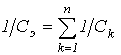 , and relation (3) holds for the equivalent values LE and CE .
As the analysis of equation (3) shows, the resonance mode can be achieved by changing the parameters L and C, as well as the frequency. On the basis of (3), the resonant frequency can be written as
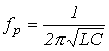 . . |
(4) |
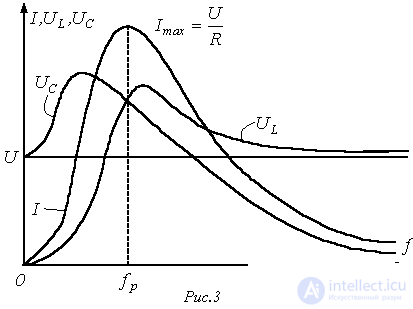
Resonance curves are the dependences of current and voltage on frequency. As an example, Fig. 3 shows typical curves I(f);  and
and  for the circuit in Fig. 1 at U=const.
An important characteristic of a resonant circuit is the quality factor Q, defined as the ratio of the voltage across the inductive (capacitive) element to the input voltage:
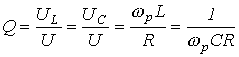 , , |
(5) |
- and characterizing the “selective” properties of the resonant circuit, in particular its bandwidth  .
.
Another parameter of a resonant circuit is the characteristic impedance, related to the quality factor by
 , , |
(6) |
or, taking (4) and (5) into account, for  we can write:
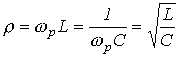 . . |
(7) |
Resonance in a circuit with parallel-connected elements
(current resonance)
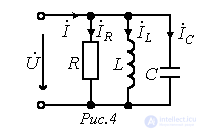
For the circuit in Fig. 4 we have
 ,
,
where
 ; ; |
(8) |
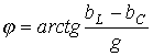 . . |
(9) |
Depending on the relationship between the values  and
and  , as in the case of series-connected elements considered above, three different cases are possible.
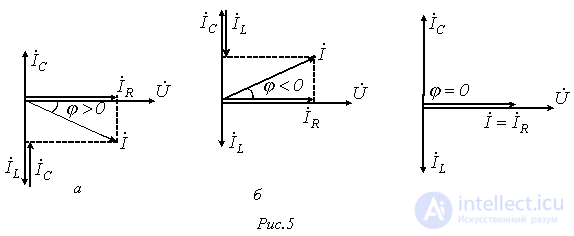
Inductance dominates in the circuit, i.e.  , and consequently
  . This mode corresponds to the phasor diagram in Fig. 5,a.
Capacitance dominates in the circuit, i.e.  , and hence
  . This case is illustrated by the phasor diagram in Fig. 5,b.
 - the case of current resonance (Fig. 5,c).
Condition for current resonance  or
or
 . . |
(10) |
In this case, as follows from (8) and (9),  . Thus, at current resonance the input admittance of the circuit is minimal, while the input impedance, on the contrary, is maximal. In particular, in the absence of the resistor R in the circuit of Fig. 4, its input impedance at resonance tends to infinity, i.e. at current resonance the current at the circuit input is minimal.
The identity of relations (3) and (5) indicates that in both cases the resonant frequency is determined by relation (4). However, expression (4) should not be used for an arbitrary resonant circuit. It is valid only for the simplest circuits with a series or parallel connection of an inductive and a capacitive element.
When determining the resonant frequency in a circuit of arbitrary configuration, or, in the general case, the relationship between the circuit parameters at resonance, one should proceed from the condition that the input impedance (input admittance) of the circuit is purely real.
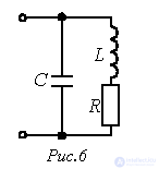
For example, for the circuit in Fig. 6 we have

Since at resonance the imaginary part of  must equal zero, the resonance condition takes the form
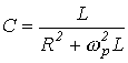 ,
,
from which, in particular, the resonant frequency is found.
Resonance in a complex circuit
The resonance condition for a complex circuit with a mixed connection of several inductive and capacitive elements, consisting in the imaginary part of the input impedance  or the input admittance
  being equal to zero, means that the equations corresponding to this condition with respect to
  have several real roots, i.e. such circuits have several resonant frequencies.
When determining the resonant frequencies of a reactive two-terminal network, the analytical expression for its input reactance  or input susceptance
  should be represented as the ratio of two polynomials in powers of
  , i.e.
  or
or  . Then the roots of the equation
  give the frequency values corresponding to voltage resonances, and the roots of the equation
  give the frequency values at which current resonances occur. The total number of resonant frequencies in a circuit is one less than the number of inductive and capacitive elements in the circuit obtained from the original one by reducing it (through equivalent transformations) to a circuit with the minimum number of these elements. A characteristic feature here is that voltage-resonance and current-resonance modes alternate.
As an example, let us determine the resonant frequencies for the circuit in Fig. 7. The expression for the input impedance of this circuit has the form

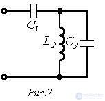
From solving the equation  we obtain the frequency
  , corresponding to voltage resonance, and from solving the equation
  - the frequency
 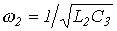 , corresponding to current resonance.
References
Review questions and problems
Answer:  .
.
Answer:  .
.
 to hold in the circuit of Fig. 1?
Comments