
Lecture
The characteristic equation is set up for the circuit after switching. It can be obtained in the following ways:
Using the first method, in the previous lecture a differential equation was obtained with respect to the voltage  across the capacitor for a series R-L-C circuit, on the basis of which the characteristic equation is written.
It should be noted that, since a linear circuit is governed by a single unified transient process, the roots of the characteristic equation are common to all the free components of the voltages and currents of the circuit's branches whose parameters enter into the characteristic equation. Therefore, in the first method of setting up the characteristic equation, any variable may be chosen as the one with respect to which it is written.
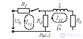
We will consider the application of the second and third methods of setting up the characteristic equation using the circuit of Fig. 1 as an example.
Setting up the characteristic equation by the input-impedance method consists of the following:
the input impedance of the circuit at alternating current is written;
jw is replaced by the operator p;
the resulting expression  is set equal to zero.
Equation

coincides with the characteristic equation.
It should be emphasized that the input impedance can be written with respect to a break at any branch of the circuit. In this case the active two-terminal network is replaced by a passive one, by analogy with the equivalent-generator method. This method of setting up the characteristic equation assumes the absence of magnetically coupled branches in the circuit; if such branches are present, they must first be decoupled.
For the circuit of Fig. 1, with respect to the source terminals
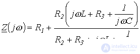 .
.
Replacing jw with p and setting the resulting expression equal to zero, we write
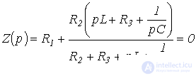
or
 . . |
(1) |
When setting up the characteristic equation on the basis of the expression for the principal determinant, the number of algebraic equations on which it is based equals the number of unknown free components of the currents. Algebraization of the original system of integro-differential equations, set up, for example, on the basis of Kirchhoff's laws or by the mesh-current method, is carried out by replacing the symbols of differentiation and integration, respectively, with multiplication and division by the operator p. The characteristic equation is obtained by setting the resulting determinant equal to zero. Since the expression for the principal determinant does not depend on the right-hand sides of the system of non-homogeneous equations, it can be set up on the basis of the system of equations written for the total currents.
For the circuit of Fig. 1, the algebraized system of equations based on the mesh-current method has the form
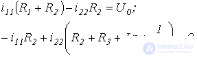
From this, the expression for the principal determinant of this system is
 .
.
Setting D equal to zero, we obtain a result analogous to (1).
General procedure for calculating transient processes by the classical method
In the general case, the procedure for calculating transient processes by the classical method includes the following steps:
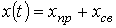 . . |
(2) |
Examples of calculating transient processes by the classical method
1. Transient processes in an R-L circuit when it is connected to a voltage source
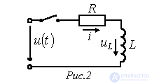
Such processes occur, for example, when electromagnets, transformers, electric motors, etc. are connected to a power supply.
Let us consider two cases:
a) 
b)  .
.
According to the procedure discussed, for the current in the circuit of Fig. 2 we can write
 . . |
(3) |
Then for the first case the forced component of the current is
 . . |
(4) |
The characteristic equation
 ,
,
from which  and the time constant
 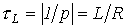 .
.
Thus,
 . . |
(5) |
Substituting (4) and (5) into relation (3), we write
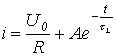 .
.
In accordance with the first switching law  . Then
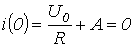 ,
,
from which  .
.
Thus, the current in the circuit during the transient process is described by the equation
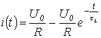 ,
,
and the voltage across the inductor – by the expression
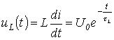 .
.
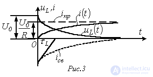
The qualitative shape of the curves  and
and  , corresponding to the solutions obtained, is shown in Fig. 3.
For the second type of source, the forced component is calculated using the symbolic (phasor) method:
 ,
,
where  .
.
From this
 .
.
The expression for the free component does not depend on the type of voltage source. Consequently,
 .
.
Since  , then
 .
.
Thus, finally we obtain
 . . |
(6) |
Analysis of the resulting expression (6) shows:
 the integration constant A=0. Thus, in this case the switching will not cause a transient process, and a steady-state mode will arise in the circuit immediately.
 the free component is maximal in magnitude. In this case the transient current reaches its greatest value.
If  is significant in magnitude, then over half a period the free component does not decrease substantially. In this case the maximum value of the transient current
  can substantially exceed the amplitude of the steady-state current. As can be seen from Fig. 4, where
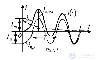
 , the current reaches its maximum after approximately
  . In the limit, as
 .
.
Thus, for a linear circuit the maximum value of the current during the transient mode cannot exceed twice the amplitude of the forced current:  .
.
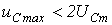
Similarly, for a linear circuit with a capacitor: if at the instant of switching the forced voltage equals its amplitude value and the circuit's time constant  is sufficiently large, then after approximately half a period the voltage on the capacitor reaches its maximum value
  , which cannot exceed twice the amplitude of the forced voltage:
  .
.
2. Transient processes when disconnecting an inductor from a power source
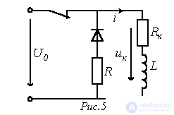
When the switch in the circuit of Fig. 5 is opened, the forced component of the current through the inductor  .
.
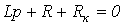
The characteristic equation
 ,
,
from which  and
and 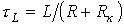 .
.
In accordance with the first switching law
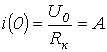 .
.
Thus, the expression for the current in the transient mode is

and the voltage across the inductor
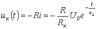 . . |
(7) |
Analysis of (7) shows that when opening circuits containing inductive elements, large overvoltages can arise, which, without special measures, can cause equipment to fail. Indeed, for 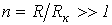 the magnitude of the voltage across the inductor at the instant of switching will exceed the source voltage many times over:
  . In the absence of a damping resistor R, this voltage is applied to the opening contacts of the switch, causing an arc to form between them.
3. Charging and discharging a capacitor
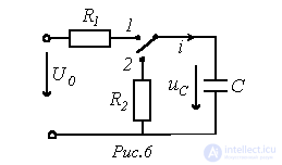
When the switch is moved to position 1 (see Fig. 6), the process of charging the capacitor begins:
 .
.
The forced component of the voltage across the capacitor  .
.
From the characteristic equation

the root 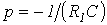 is determined. From this the time constant
  .
.
Thus,
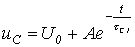 .
.
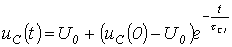
At t=0 the voltage across the capacitor equals  (in the general case, by the instant of switching the capacitor may already be charged, i.e.
  ). Then
 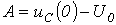 and
and
 .
.
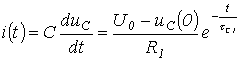
Correspondingly, for the charging current we can write
 .
.
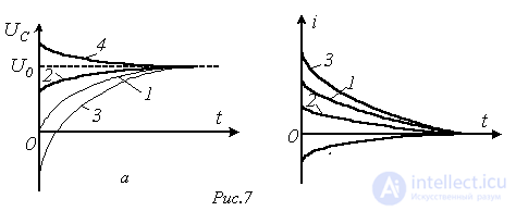
Depending on the value of  : 1 -
: 1 -  ; 2 -
; 2 -  ; 3 -
; 3 -  ; 4 -
; 4 -  - four types of transient-process curves are possible, as illustrated in Fig. 7.
When the capacitor is discharged onto a resistor  (the switch in Fig. 6 is moved to position 2)
  . The time constant
  .
.
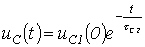
Then, assuming that by the instant of switching the capacitor was charged to a voltage of  (in the particular case
  ), for the voltage across it in the transient mode we can write
 .
.
Correspondingly, the discharge current
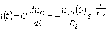 . . |
(8) |
As can be seen from (8), to avoid significant surges in the discharge current, the value of  should be sufficiently large.
In conclusion, we note that the processes of charging and discharging a capacitor are used in sawtooth-voltage generators, which are widely used in automation. For this purpose, the switch in the circuit of Fig. 6 is replaced with an electronic one.
References
Review questions
Answer:  .
.
Answer:  .
.
 is broken.
 the transient in it will be aperiodic, if
  .
. in the circuit in Fig. 9, if
  ,
,  ,
,  ,
,  .
.
Comments