
Lecture
Knowing the response of a circuit to a unit disturbing action, i.e. the transient-conductance function  or (and) the transient function with respect to voltage
  , one can find the response of the circuit to an action of arbitrary shape. The method is based on the superposition principle – the method of calculation using the Duhamel integral.
When using the Duhamel integral, to separate the variable with respect to which integration is performed from the variable determining the instant of time at which the current in the circuit is sought, the first is conventionally denoted as  , and the second as t.
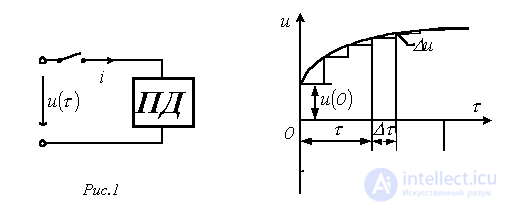
Suppose that at instant  a source with voltage
  of arbitrary shape is connected to a circuit with zero initial conditions (a passive two-terminal network PD in fig. 1). To find the current
  in the circuit, let us replace the original curve with a stepped one (see fig. 2), after which, taking into account that the circuit is linear, we sum the currents due to the initial voltage jump
  and all the voltage steps up to the instant t, which come into action with a time delay.
At instant t, the component of the total current determined by the initial voltage jump  is equal to
  .
.
At instant  there occurs a voltage jump
 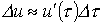 , which, taking into account the time interval from the start of the jump to the instant of interest t, produces a current component
  .
.
The total current  at instant t is obviously equal to the sum of all the current components due to the individual voltage jumps, taking
  into account, i.e.
 .
.
Replacing the finite time increment  with an infinitesimal one, i.e. going from a sum to an integral, we write
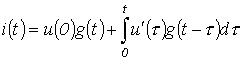 . . |
(1) |
Relation (1) is called the Duhamel integral.
It should be noted that the Duhamel integral can also be used to determine voltage. In that case, instead of the transient conductance  , (1) will contain the transient function with respect to voltage.
Sequence of calculation using
the Duhamel integral
 (or
(or  ) for the circuit under study.
 (or
(or  ) by formally replacing t with
  .
. .
.As an example of using the Duhamel integral, let us determine the current in the circuit of fig. 3, which was calculated in the previous lecture using the switch-on formula.
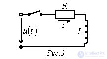
Initial data for the calculation: 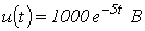 ,
,  ,
,  .
.
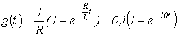 .
.

 .
.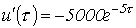 .
.
The result obtained is similar to the expression for the current found in the previous lecture on the basis of the switch-on formula.
State-variable method
The equations of electromagnetic state form a system of equations that determines the operating mode (state) of an electric circuit.
The state-variable method is based on the orderly formulation and solution of a system of first-order differential equations that are solved for the derivatives, i.e. written in a form most convenient for applying numerical integration methods implemented by computing means.
The number of state variables, and hence the number of state equations, equals the number of independent energy-storage elements.
Two basic requirements are placed on the state equations:
-independence of the equations;
-the possibility of recovering, from the state variables (the variables with respect to which the state equations are written), any other variables.
The first requirement is satisfied by a special procedure for formulating the state equations, which will be discussed further below.
To satisfy the second requirement, the flux linkages (currents in branches with inductive elements) and the charges (voltages) on capacitors should be adopted as state variables. Indeed, knowing the law of variation of these variables with time, they can always be replaced by EMF and current sources with known parameters. The rest of the circuit turns out to be resistive, and hence can always be calculated once the source parameters are known. In addition, the initial values of these variables belong to the independent ones, i.e. in general they are simpler to calculate than others.
When calculating by the state-variable method, in addition to the state equations themselves, which relate the first derivatives 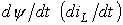 and
and 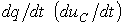 to the variables themselves
  and
and  and to the sources of external actions – EMF and current – it is necessary to compose a system of algebraic equations relating the sought quantities to the state variables and the sources of external actions.
Thus, the complete system of equations in matrix form is
 ; ; |
(2) |
 . . |
(3) |
Here  and
and  - column matrices of the state variables and of their first time derivatives, respectively;
  - the column matrix of the sources of external actions;
  - the column matrix of the output (sought) quantities;
  - a square n x n matrix of parameters (where n is the number of state variables), called the Jacobian matrix;
  - a rectangular matrix relating the sources to the state variables (the number of rows equals n, and the number of columns equals the number of sources m);
  - a rectangular matrix relating the state variables to the sought quantities (the number of rows equals the number of sought quantities k, and the number of columns equals n);
  - a rectangular k x m matrix relating the input to the output.
The initial conditions for equation (2) are given by the vector of initial values  (0).
(0).
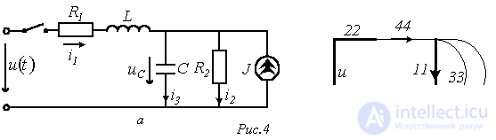
As an example of setting up the state equations, consider the circuit in fig. 4,a, in which it is required to determine the currents  and
and  .
.
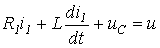
By Kirchhoff's laws, for this circuit we write
 ; ; |
(4) |
 ; ; |
(5) |
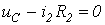 . . |
(6) |
Since 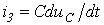 taking relation (6) into account, we rewrite equations (4) and (5) in the form
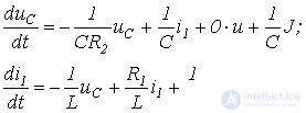
or in matrix form
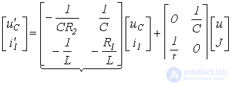
| A | B |
A matrix equation of the form (3) follows from relations (4) and (6):
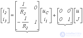
| C | D |
Vector of initial values  (0)=
(0)=  .
.
Direct use of Kirchhoff's laws when formulating the state equations for complex circuits can turn out to be difficult. For this reason a special procedure for the orderly formulation of the state equations is used.
Procedure for formulating the state equations
This procedure includes the following main steps:
1. A directed graph of the circuit is constructed (see fig. 4,b), on which a tree is selected that covers all capacitors and voltage sources (EMF). Resistors are included in the tree as needed, so that the tree covers all nodes. The link branches include the inductors, current sources, and the remaining resistors.
2. The branches of the graph (and the elements in the circuit) are numbered in the following sequence: first the sections of the graph (circuit) containing capacitors are numbered, then the resistors included in the tree; next come the link branches with resistors and, finally, the branches with inductive elements (see fig. 4,b).
3. A table describing the connection of the elements in the circuit is constructed. In the first row of the table (see table 1) the capacitive and resistive elements of the tree, as well as the voltage sources (EMF), are listed. In the first column the resistive and inductive elements of the link branches, as well as the current sources, are listed.
Table 1. Connection table
|
11 |
22 |
u |
|
|
33 |
-1 |
0 |
0 |
|
44 |
1 |
1 |
1 |
|
J |
1 |
0 |
The procedure for filling in the table consists in mentally closing the tree branches one at a time using link branches until a loop is obtained, followed by traversing the loop according to the orientation of the corresponding link branch. Graph branches whose orientation coincides with the direction of loop traversal are entered with a «+» sign, and branches with the opposite orientation with a «-» sign.
The table is expanded both by columns and by rows. In the first case, equations by Kirchhoff's first law are obtained; in the second, by the second law.
In the case under consideration (the equality  is trivial)
 ,
,
from which, in accordance with the numbering of currents in the original circuit
 .
.
When expanding the connection table by rows, the voltages on the passive elements must be taken with signs opposite to those in the table:
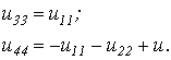 |
(7) |
These equations coincide, respectively, with relations (6) and (5).
From (7) it follows directly that
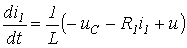 .
.
Thus, by a formalized procedure, equations analogous to those set up above using Kirchhoff's laws have been obtained.
References
Review questions and problems
Answer:  at
at  ;
; 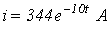 at
at  .
.
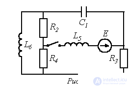
 the voltage at the input of the circuit instantaneously drops to zero. Determine the current in the circuit.
 ,
,  ,
, 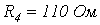 ,
,  ,
,  ,
, 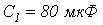 .
.
Answer:
| A | 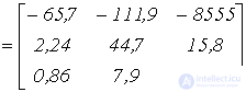 |
| B |  |

Comments