
Lecture
In cases where, in analyzing the transient process, the energy sources can be divided into nearby and remote ones, the concept of infinite-power systems can be introduced to simplify the calculations.
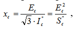
Infinite-power systems are characterized by an EMF  and a reactance
 . The EMF is taken as the voltage at the point beyond which it is practically independent of the processes in the circuit under consideration, and the reactance:
 ,
,
where  – is the short-circuit current from the infinite-power system;
 –is the subtransient short-circuit power.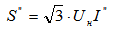
As a first approximation for estimating the active resistance of the system, it is taken that  .
.
In cases where the part of the circuit under consideration has two-sided feed, it makes sense to introduce two infinite-power systems (Fig. 5.1). The initial data will be the short-circuit currents at the points where the infinite-power systems are connected:
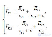
Given the known values of 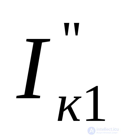 and
and it is possible to determine the reactance of systems
1 and 2.
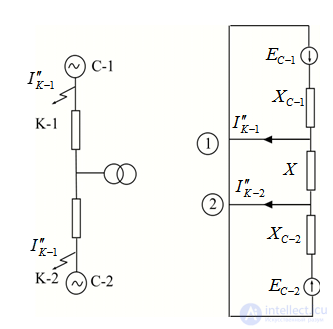
Fig. 5.1. Equivalent circuits with two-sided feed
If the short-circuit currents are unknown, they can be determined from the breaking capacity of the circuit breaker located at the point where the infinite-power system is connected: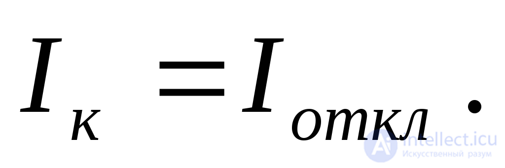
If, for a short circuit near large generators, the surge factor is very close to 2, then as the fault location becomes more remote it generally decreases, and does so more sharply the more overhead lines, and especially cable lines, are involved.
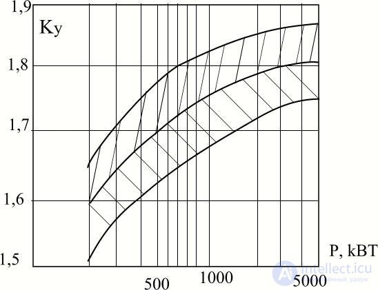
When induction motors are taken into account as additional power sources, it must be kept in mind that the decay of the periodic and aperiodic components of the current they generate occurs with approximately the same time constants. Therefore, the surge factor for induction motors usually accounts for the simultaneous decay of both current components.
The dependence of the surge factor of induction motors on their power is shown in Fig. 5.2, where the shaded zone indicates the range of deviation of this factor from the average value (the mean curve).
Example 5.1. The circuit shown in Fig. 5.3 contains six voltage levels. The sectionalizing circuit breaker B is normally open. Element data for the circuit:
generator G 176,5 MVA, 15,75 kV, 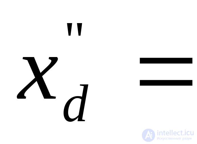 0,15;
0,15;
Fig. 5.2. Dependence of the surge factor on power for induction motors
transformer T-1 180 MVA, 242/15,75 kV,  ;
;
transformer T-2 90 MVA, 220/38,5/11 kV,  ,
,  ,
,  ;
;
transformer T-3 120 MVA, 110/6,6 kV,  ;
;
autotransformer AT-1 120 MVA, 220/121/11 kV,  ,
, ,
, ;
;
line L-1 200 km, x = 0,4 ohm/km per single circuit;
line L-2 50 km, x = 0,4 ohm/km;
cable Cb-1 2,5 km, x = 0,08 ohm/km;
reactor R 6 kV, 500 A, x = 5%.
1. It is required to set up the equivalent circuit and express its elements in per-unit values; in doing so, perform both an exact and an approximate reduction of the elements, i.e., taking into account the actual rated voltages (according to the actual transformation ratios of the transformers and autotransformers), and approximately, when these voltages are taken equal to the established average voltages of the corresponding transformation levels.
2. Determine the initial subtransient current for a three-phase short circuit occurring alternately at points K-1 and K-3, assuming that the generator was previously running at no load with rated voltage.
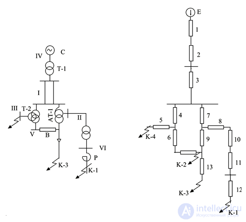
Fig. 5.3. For Example 5.1: a – original circuit, b – equivalent circuit
Solution:
Fig. 5.3, b shows the equivalent circuit with the serial numbers of all its elements indicated.
Let us take the base power as 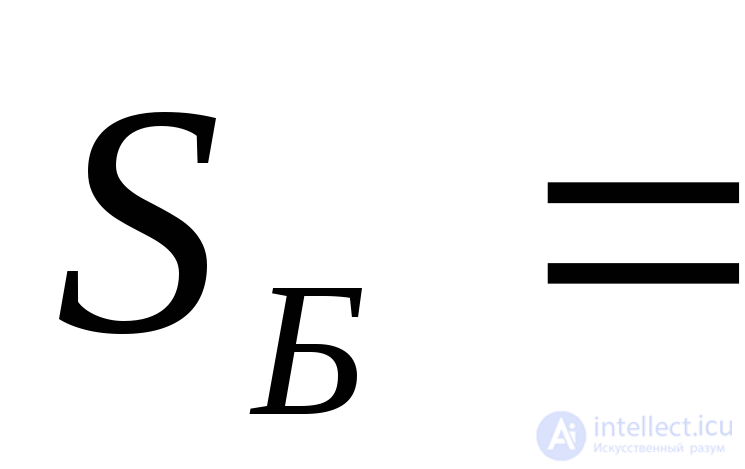 1000 MVA, and the base voltage at the first level as –
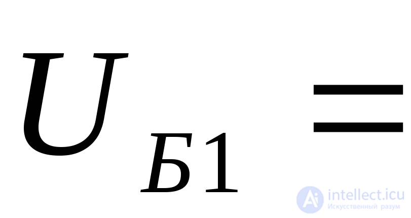 220 kV. Accordingly, the base voltages at the other levels of the circuit will be:
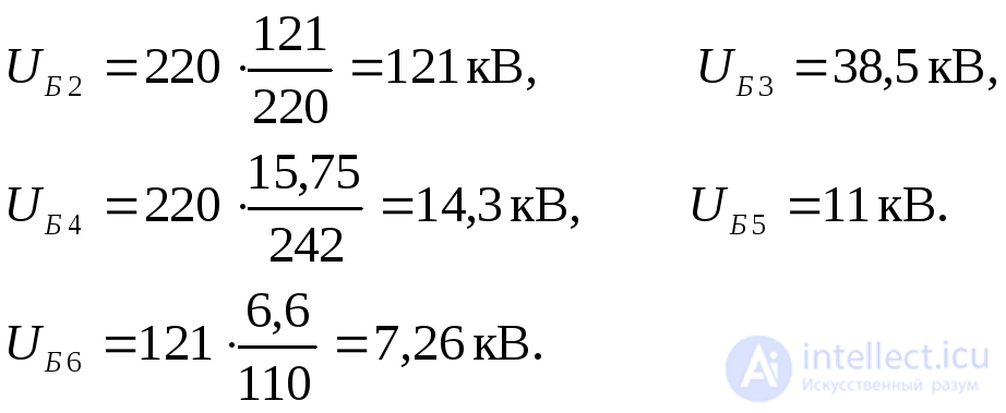
Base currents at the points where short circuits are considered:
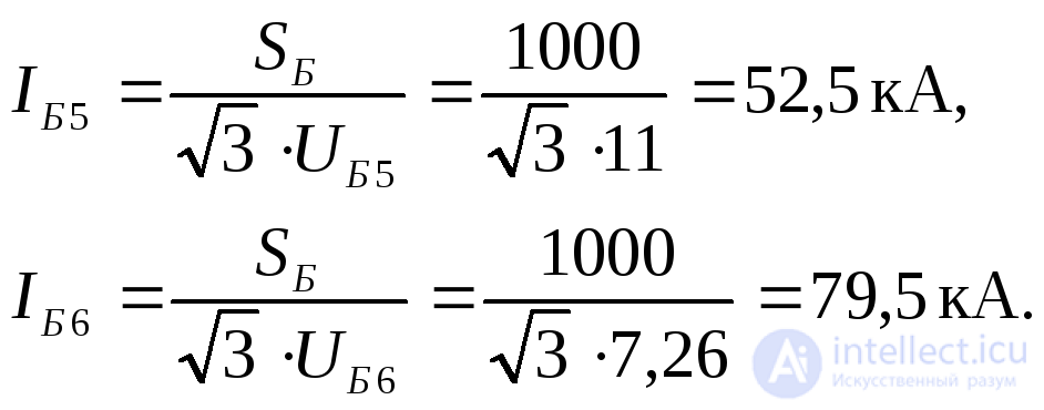
With exact reduction, the per-unit reactances under base conditions will be:
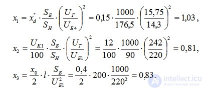
For transformer T-2:
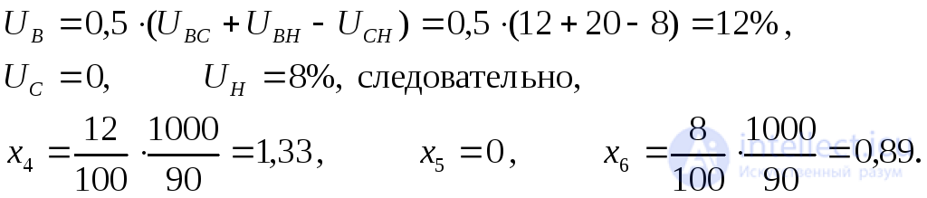
For autotransformer AT-1:
The per-unit value of the EMF –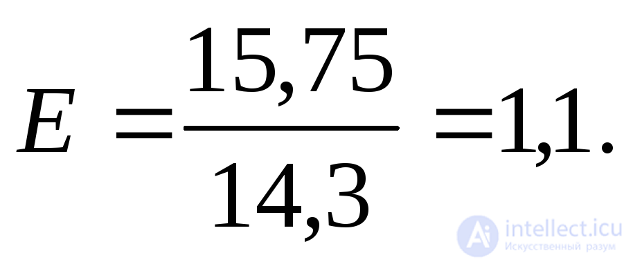
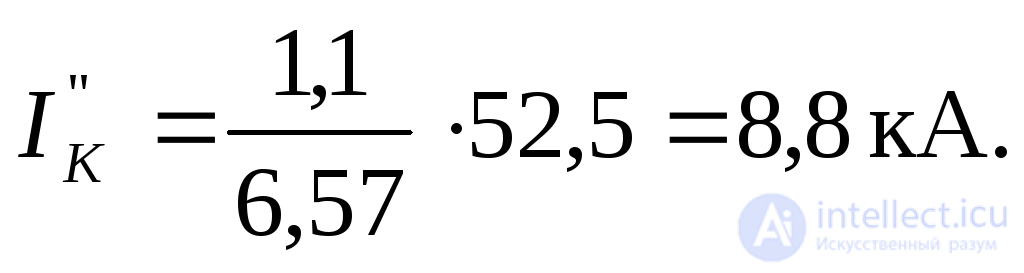
For a short circuit at point K-1:

current 
Similarly, for a short circuit at point K-3:  and the current
With approximate reduction:

Keeping  MVA, let us find the values of the base currents:

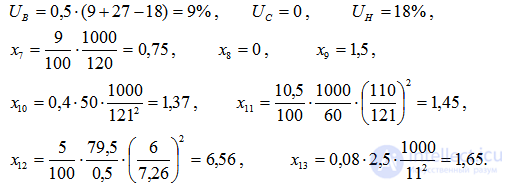
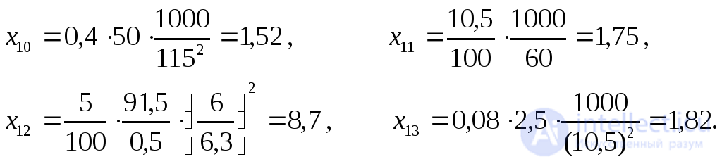
In this case, the transition to base conditions is considerably simplified. Thus, for the individual elements we will have:

For elements 4-9, the per-unit reactances reduced to base conditions remain the same as obtained above, while for the rest we have
The per-unit value of the EMF 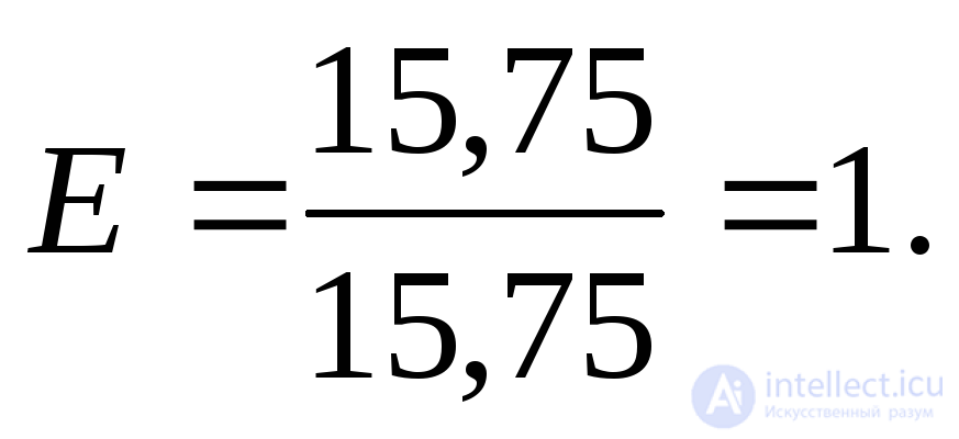
For a short circuit at point K-1:

and current 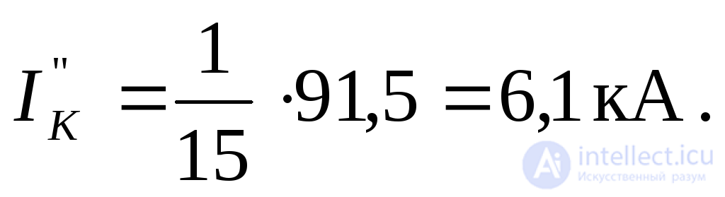
For a short circuit at point K-3:

and current 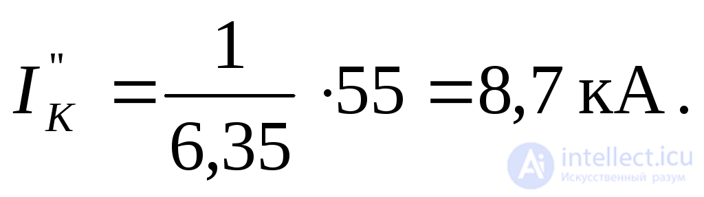
Example 5.2. For a three-phase short circuit at point K (Fig. 5.3, a), calculate the surge current at the fault location.
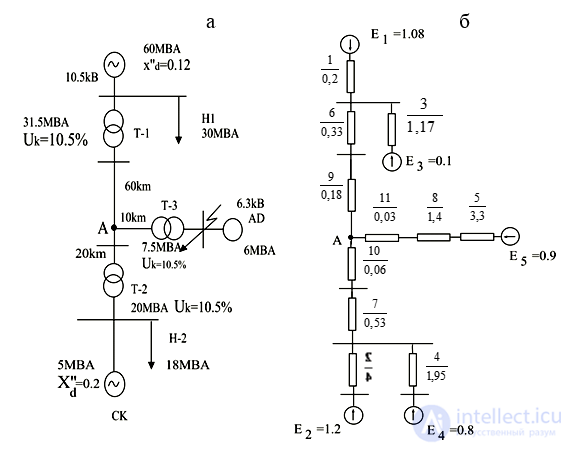
Fig. 5.4. For Example 5.2: a – original circuit; b – equivalent circuit
Let us first perform the calculation taking into account all connected loads. In this case, the circuit has the form shown in Fig. 5.3 (b), where all reactances are expressed in per-unit values at  MVA and at
 , and the per-unit EMF values are taken from the data of Table 5.1. The surge factor for a short circuit at the induction motor busbars is
 .
.
By successively transforming the equivalent circuit we find

The initial subtransient current from the side of transformer T-3, in per-unit values:
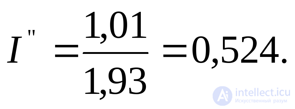
Since the residual voltage at point A is  , this already indicates that loads N-1 and N-2 are unlikely to act as power sources and, in any case, their influence is insignificant.
Now, using the data of Table 5.3, let us estimate the active resistances of the circuit elements:
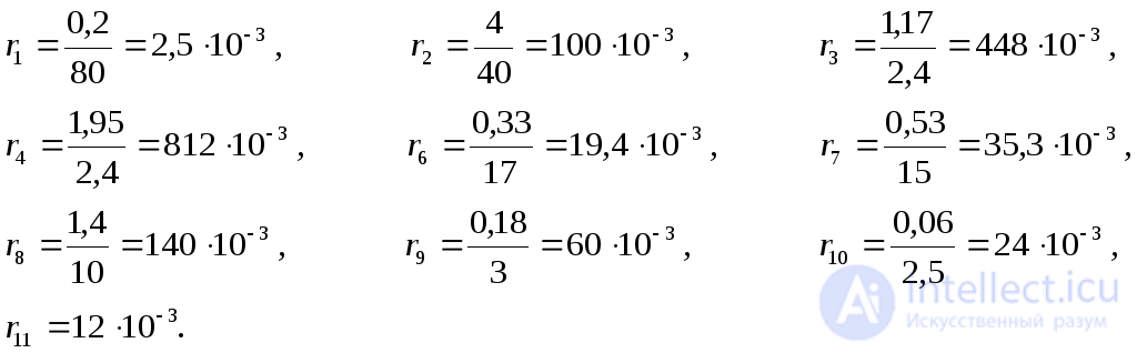
The resistances 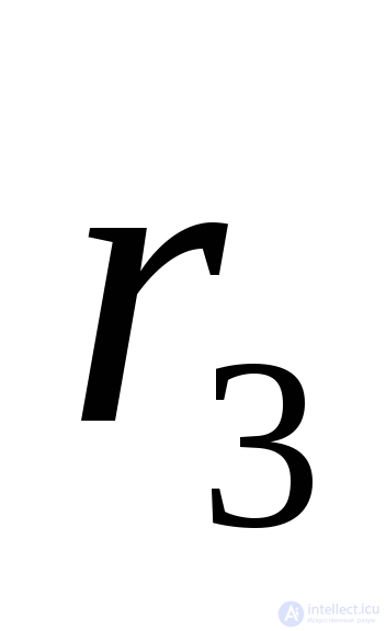 and
and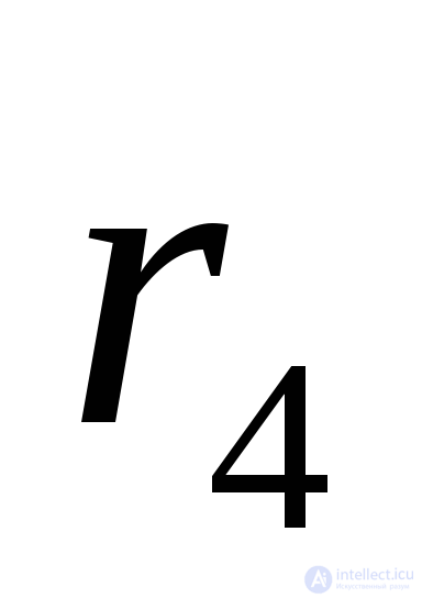 are disproportionately large compared with their parallel resistances (respectively
 and
and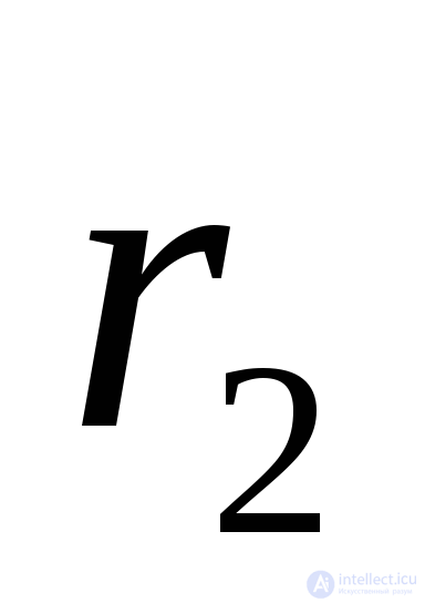 ), which allows us to take
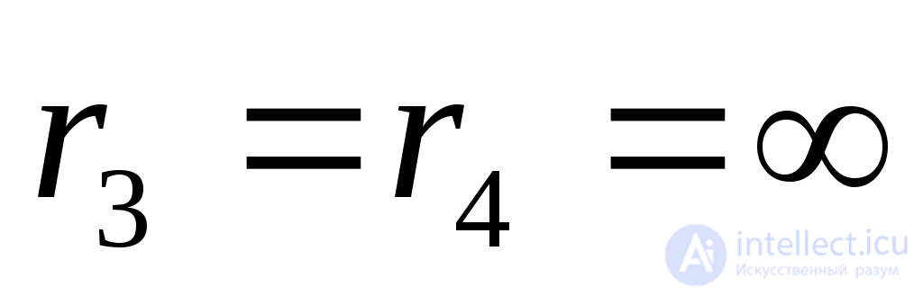 . Then the active resistance of the circuit up to the fault location from the side of transformer T-3 will be:

The ratio 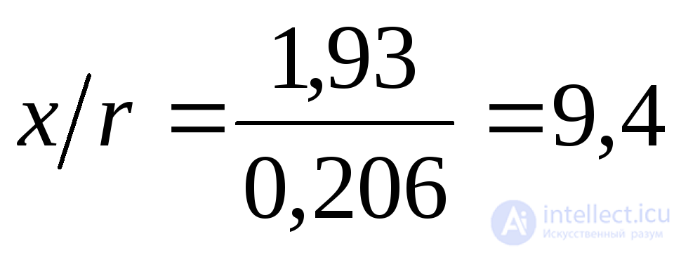 , effective time constant:
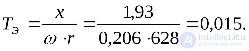
Surge factor 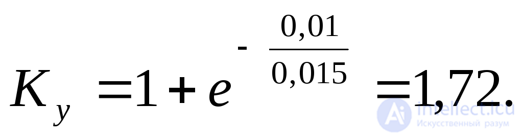
Taking into account the additional feed from induction motor AD, the required current will be:

where 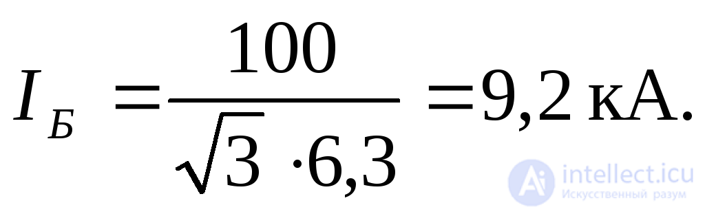
In a more simplified calculation, if loads N-1 and N-2 are neglected and it is assumed that 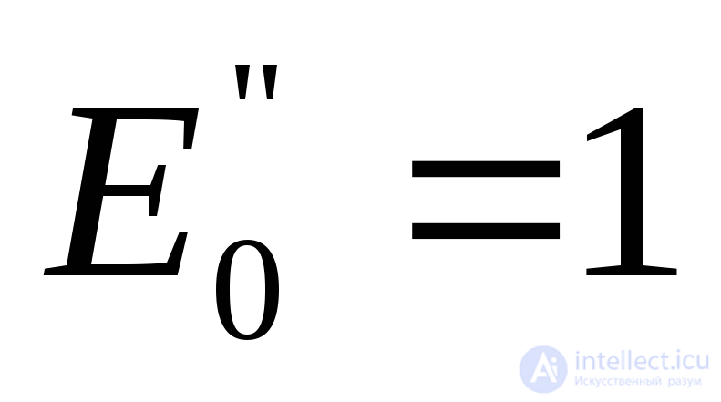 , then the overall reactance of the circuit (without the induction motor) is
 and, consequently,
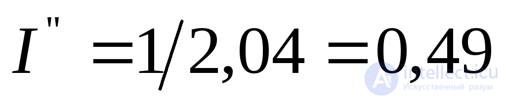 , i.e., this component of the circuit current would be 6,5% smaller than calculated earlier.
Example 5.3. Two identical induction motors are fed from the 6 kV busbars of a step-down substation (Fig.5.5), each having the parameters: 2000 kW; 6 kV, cos =0,83; efficiency=92%,
  .
.
The remaining elements are characterized by the following data:
Transformer T-1 – 15 MVA, 115,5/37 kV,  .
.
+Transformer T-2 – 7,5 MVA, 36,8/6,6 kV,  .
.
L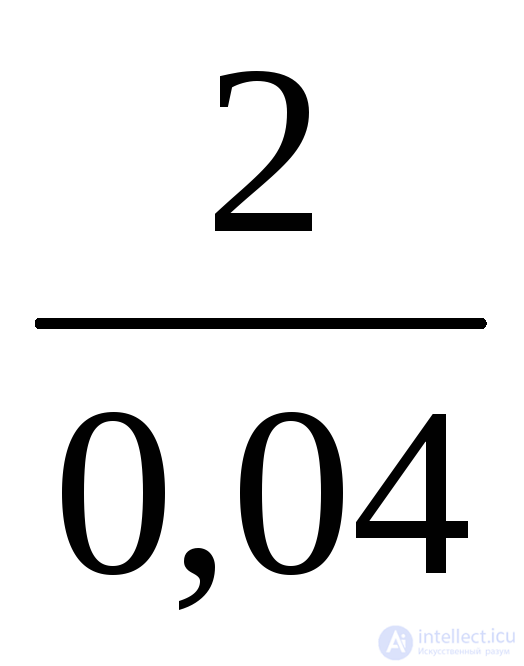 ine L – 15 km,
 ohm/km .
System S – an infinite-power source with constant voltage of 107 kV.
It is required to compare the conditions
of motor starting for the cases,
when:
a) both motors are started
simultaneously;
b) one motor is started,
while the other operates
at rated voltage with
load  at cos
 =0,8.
=0,8.
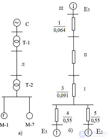
Fig.5.5. For Example 5.3: a) original circuit,
b) equivalent circuit
The comparison should be made using the magnitude of the periodic component of the starting current and the starting torque, bearing in mind that the starting torque at rated voltage is 70% of the motor's rated torque.
Solution:
Let us take  MVA,
MVA, kV. Then the base voltages at the other levels will be:

The per-unit reactances of the elements of the equivalent circuit
in Fig. 5.5,b will accordingly be:
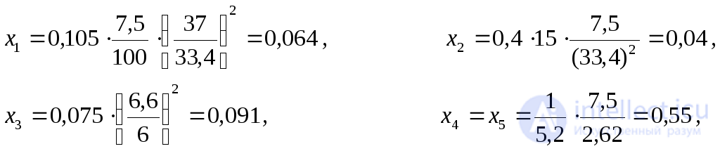
where the rated power 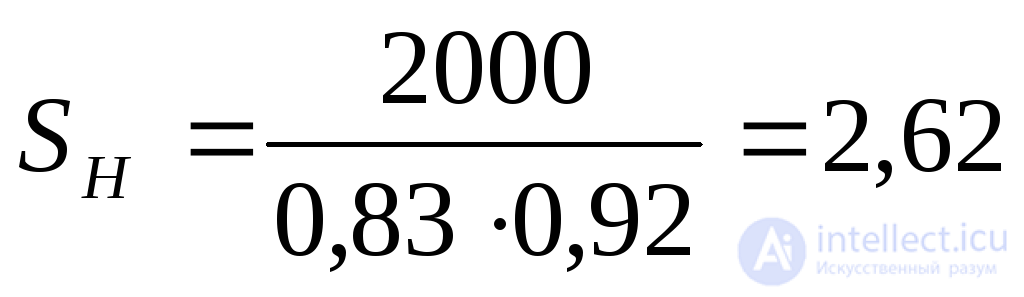 MVA.
MVA.
The system voltage in per-unit values 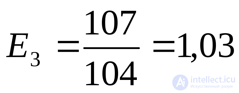 .
.
a) Simultaneous starting of two motors.
In this case, in the equivalent circuit of Fig. 5.5,b it should be
assumed that 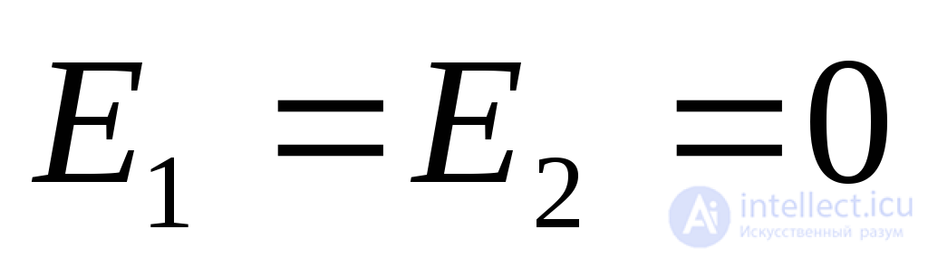 . The resulting resistance of the circuit:
 .
.
The starting current in each motor under base conditions:

or, relative to the motor's rated current, 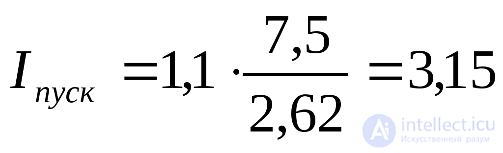 .
.
The residual voltage at the motor terminals during its starting

and, correspondingly, the motor torque during starting
 .
.
b) Starting one motor while the other is running.
Let us first find the EMF of the motor that was operating under load. Its working current under base conditions is
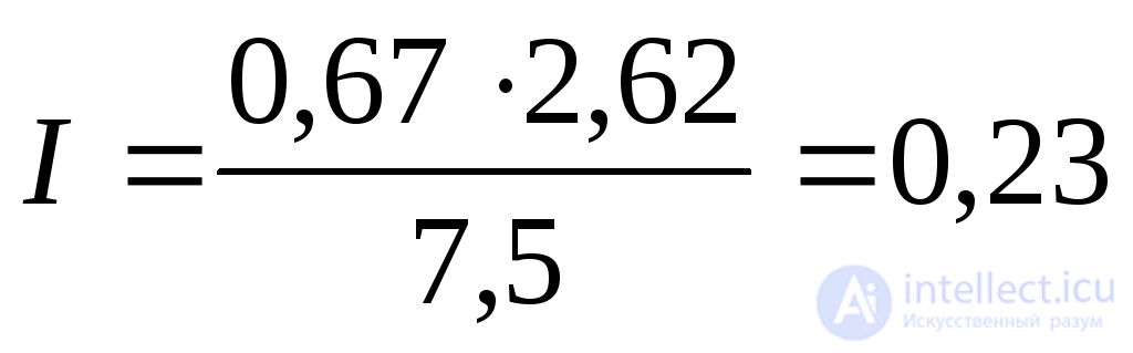 ,
,
consequently, the required EMF will be:
 .
.
The total reactance from the system side to the 6 kV busbars:
 .
.
The equivalent resistance of the circuit up to motor M-2, whose starting is being considered in this case (correspondingly 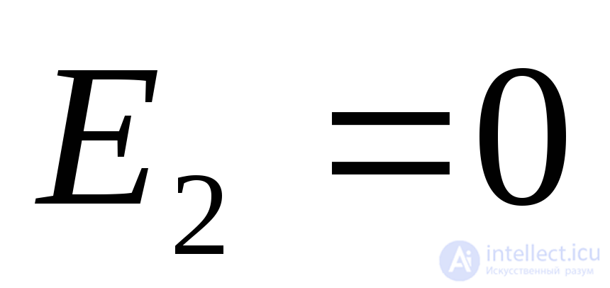 ), is
), is
 ,
,
and the equivalent EMF applied behind this resistance
 .
.
Starting current under base conditions: 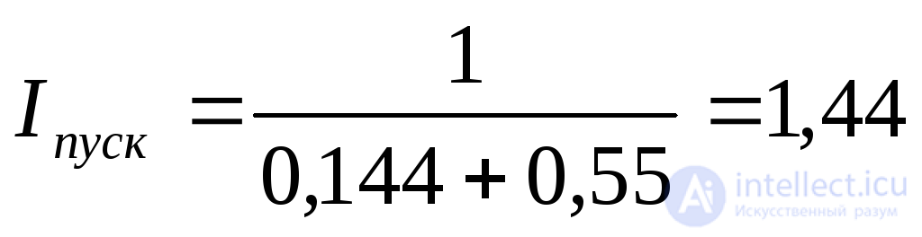
and under rated conditions 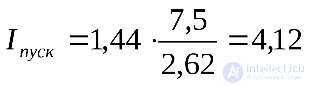 .
.
Residual voltage  .
.
The torque developed by the motor during starting

+As can be seen, compared with the conditions considered in item (a), in this case the current is greater by a factor of 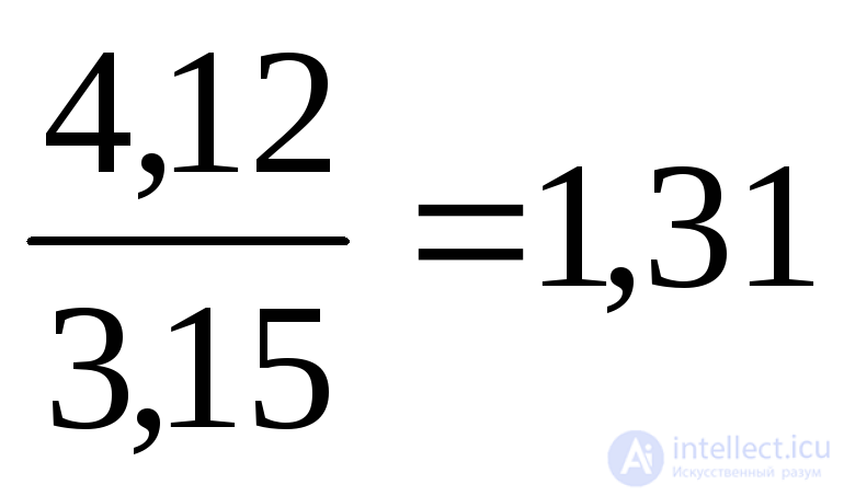 , and the starting torque – by a factor of
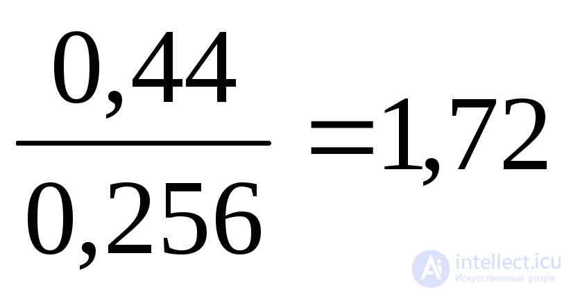 .
.

Comments